Dynamic bandwidth throttling

a bandwidth throttling and dynamic technology, applied in the field of communication networks, can solve the problems of consuming a large portion of the available bandwidth, moving data from one point, and introducing latency by buffering devices on the network, and achieve the effect of slowing down the data transmission ra

Active Publication Date: 2011-03-17
IBM CORP
View PDF128 Cites 49 Cited by
  • Summary
  • Abstract
  • Description
  • Claims
  • Application Information

AI Technical Summary

Benefits of technology

[0011]An embodiment of the invention provides a technique that keeps track of an approximation of the bandwidth of the narrowest link in a network by watching how fast data gets to the other end and then back again. The rate of data transmission is limited according to this approximation. The technique also

Problems solved by technology

A basic problem in electronic networks is moving data from one point to another.
Another concern is limiting data to a rate at which the network performs well, instead of moving data across the network because there is a supposed need to hurry.
This approach consumes a lar

Method used


Image

  • Dynamic bandwidth throttling
  • Dynamic bandwidth throttling
  • Dynamic bandwidth throttling

Examples


Embodiment Construction

Effective Bandwidth

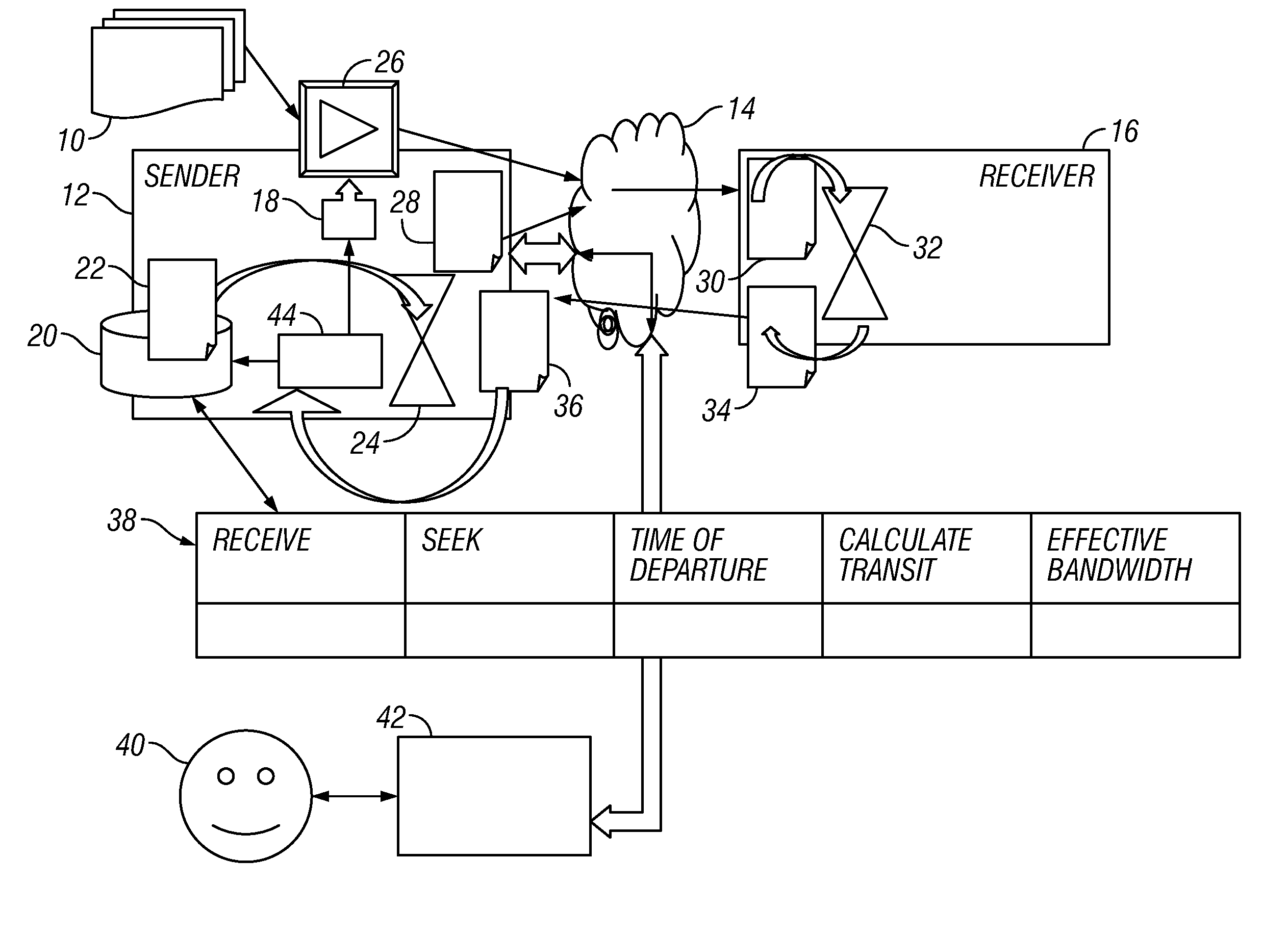
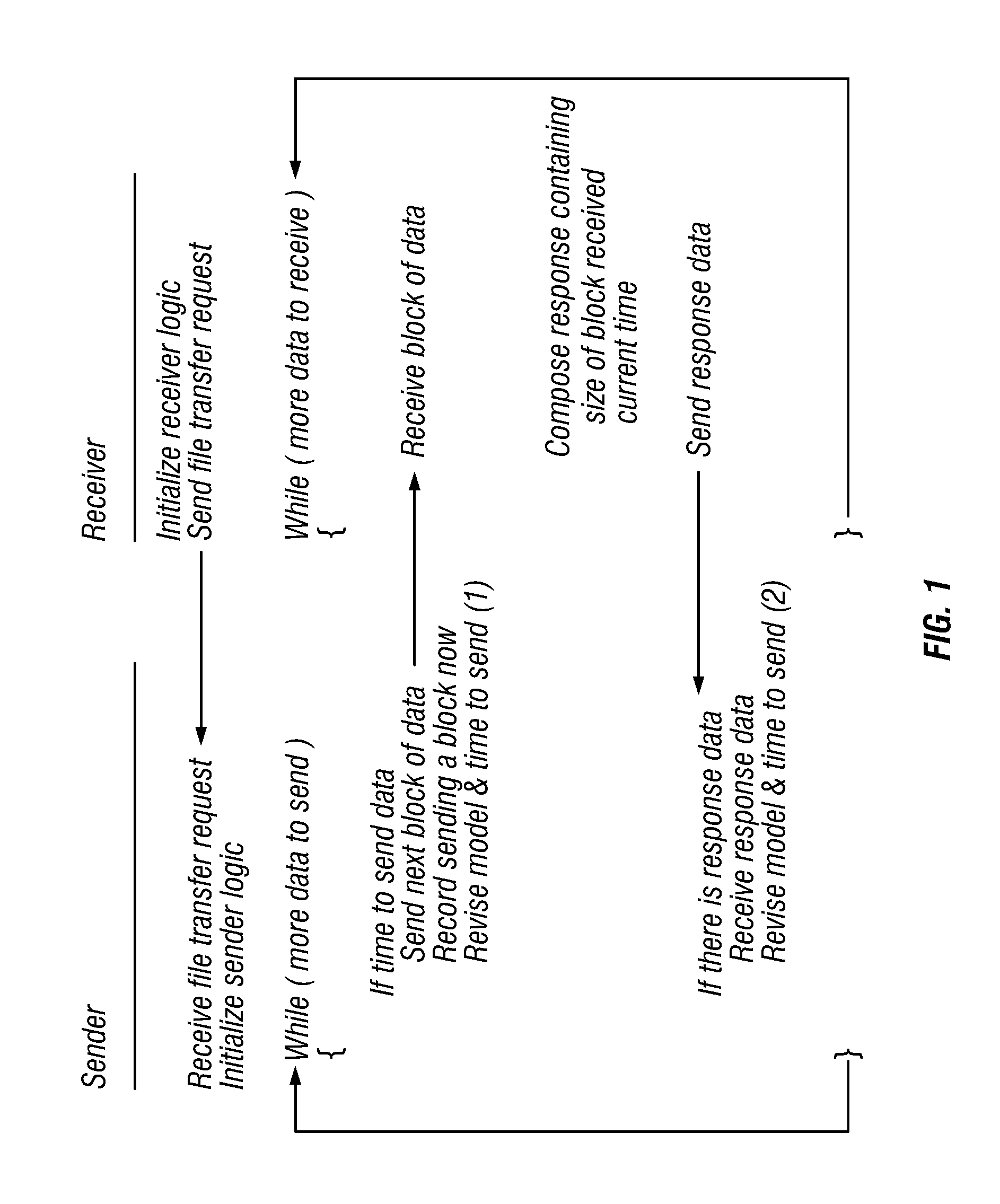
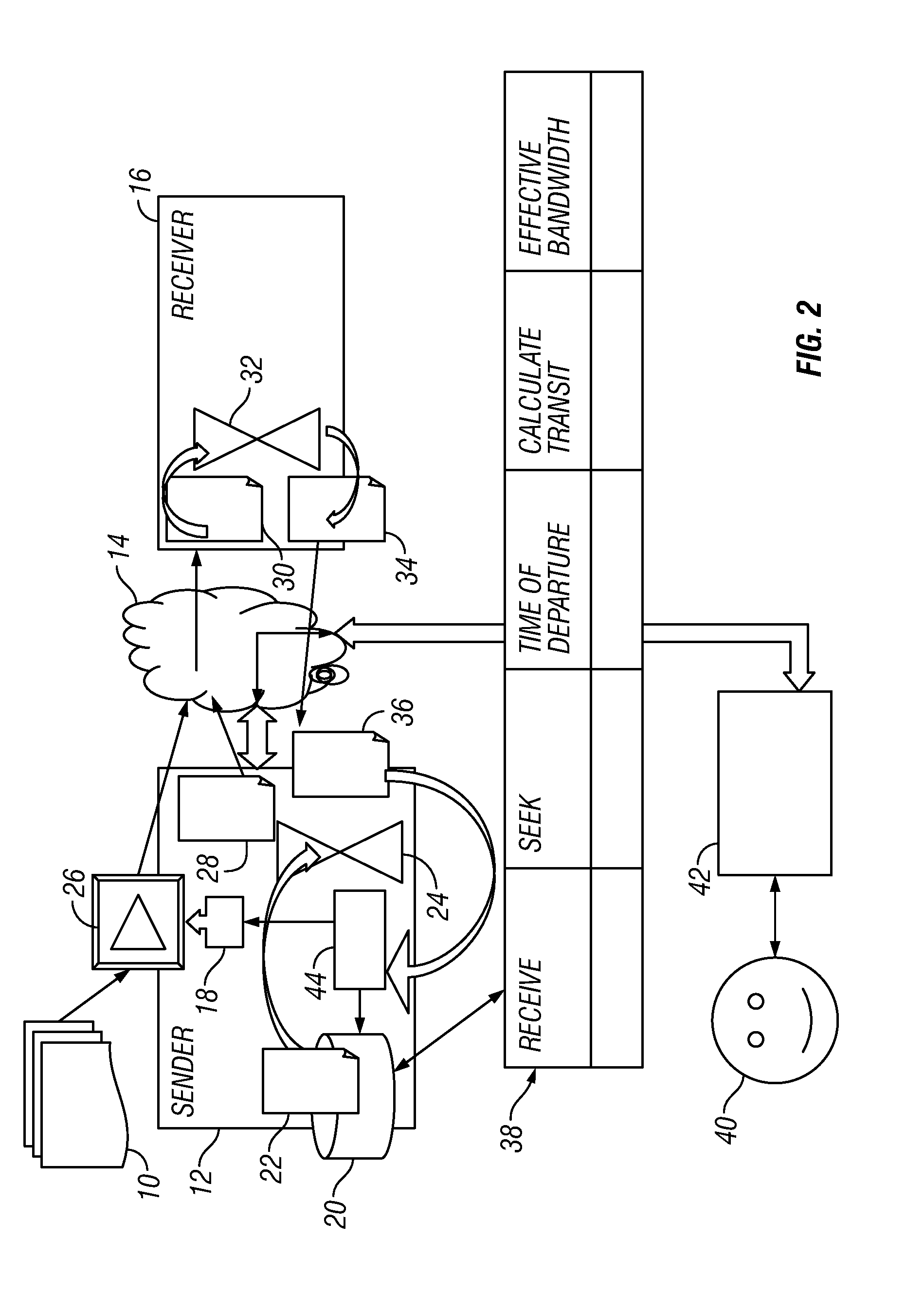
[0015]An embodiment of the invention provides a technique that keeps track of an approximation of the bandwidth of the narrowest link in a network by watching how fast data gets to the other end and back again. The rate of data transmission is limited according to the approximation. FIG. 1 is a flow diagram showing an implementation of a bandwidth throttling mechanism according to the invention.

Dynamic Capacity

[0016]An embodiment also keeps track of the dynamic capacity of the link, i.e. the amount of data that can be in-flight at the same time, neglecting any buffers. The technique looks at how much data there is in-flight and, if there is more data in flight than the dynamic capacity of the network, the data transmission rate is slowed down to avoid having more data in flight than the dynamic capacity of the network. This approach limits the impact of data transmission on latency for other uses of the network because it only looks at the effect of a local load o...


PUM


Abstract

An approximation of the bandwidth of the narrowest link in a network is determined by watching how fast data gets to the other end and then back again. The rate of data transmission is limited according to this approximation. Dynamic capacity of the link, i.e. the amount of data that can be in-flight at the same time, neglecting any buffers, is also tracked. The technique looks at how much data is in-flight and, if there is more data in flight than the dynamic capacity of the network, the data transmission rate is slowed down.

Description

CROSS REFERENCE TO RELATED APPLICATIONS[0001]This application claims priority to U.S. provisional application Ser. No. 61 / 242,278, filed 14 Sep. 2009, which application is incorporated herein in its entirety by this reference thereto.BACKGROUND OF THE INVENTION[0002]1. Technical Field[0003]The invention relates to communications networks. More particularly, the invention relates to a technique for dynamic bandwidth throttling in communications networks.[0004]2. Description of the Background Art[0005]A basic problem in electronic networks is moving data from one point to another. There are typically two goals in this regard: one goal is to get the data across the network quickly; and the other goal is to let other people's data go across the network quickly, without one person's data getting in the way of another person's data. Often, one person's data (person A) is among the less urgent data in the network. In this case, it is desirable to have the other persons' data traverse the n...

Claims


Application Information

Patent Timeline
IPC IPC(8): G06F15/16
CPCH04L43/0894H04L47/25H04L43/106H04L12/12H04L45/122H04L45/64
Inventor LIPPINCOTT, LISA ELLENLINCROFT, PETER JAMESGOODROW, DENNIS SIDNEY
Owner IBM CORP
Why Eureka
Try Eureka