Knob with lock mechanism
a technology of knobs and locks, applied in the direction of mechanical control devices, domestic stoves or ranges, instruments, etc., can solve the problems of increasing the amount of heat, dangerous repercussions, and accidentally turning on the stove burner
- Summary
- Abstract
- Description
- Claims
- Application Information
AI Technical Summary
Benefits of technology
Problems solved by technology
Method used
Image

Examples
first embodiment
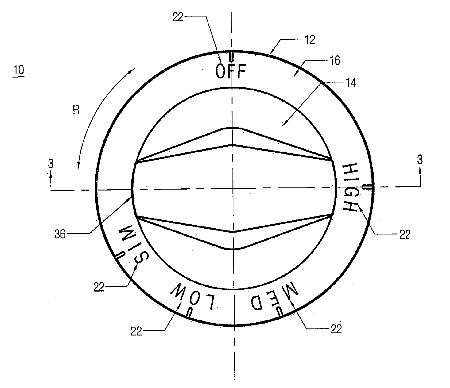
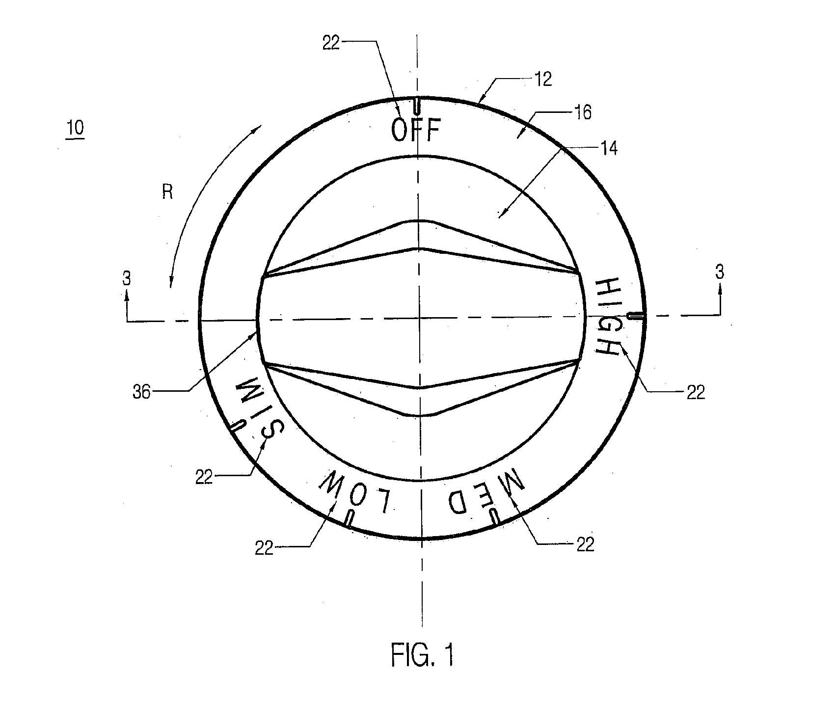
[0039]FIG. 3A is an exemplary illustration of a sectional view of control knob 10 in a (default or natural) locked position. As shown, mount portion 16 of body 12 may comprise a diagonally flared wall that extends in an outward direction from grasp portion 14.
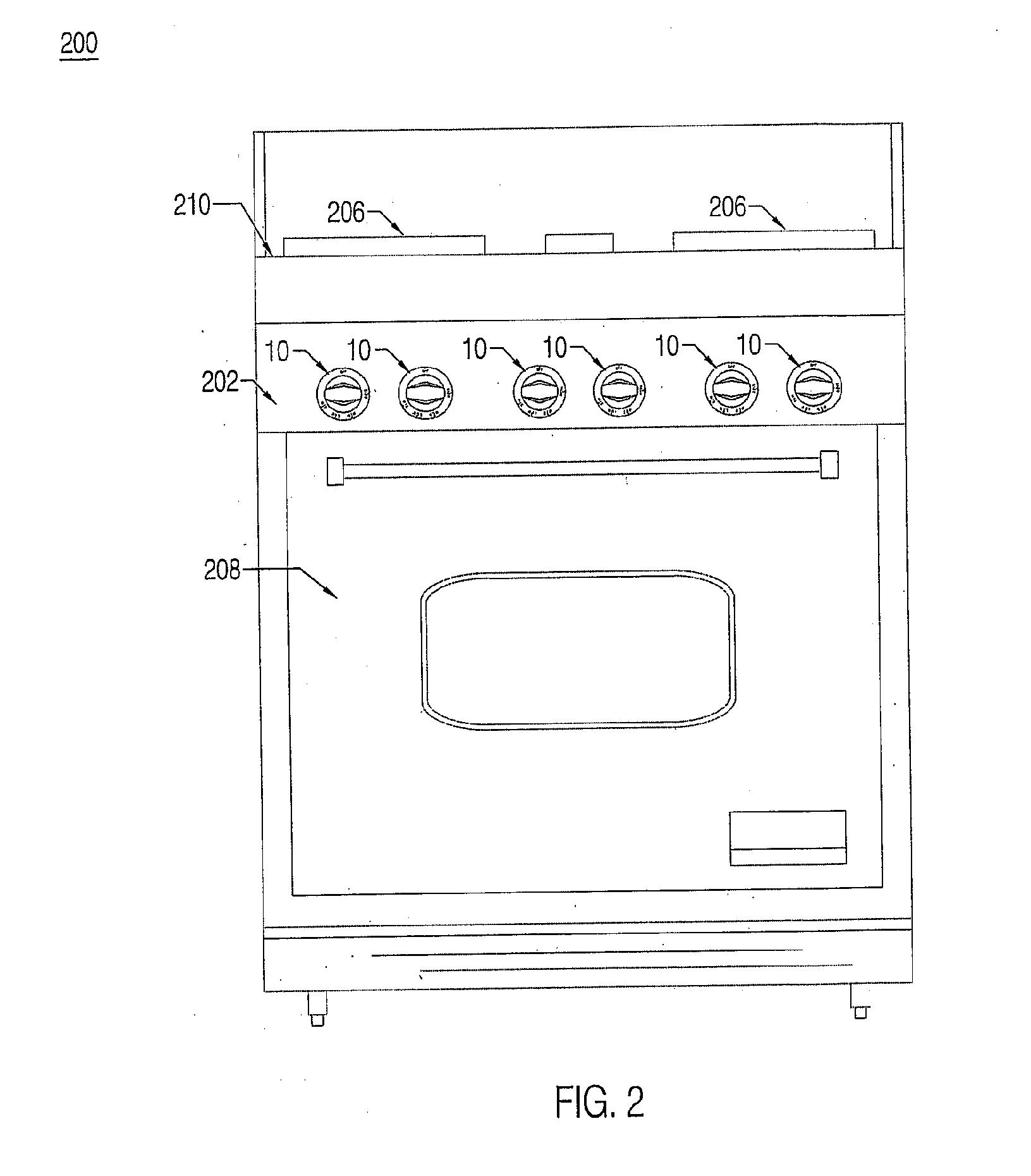
[0040]In one implementation, a center portion 18 of knob 10 may comprise an integrally-formed portion of body 12, or may comprise a portion separate from body 12. Center portion 18 may comprise a first (upper) part 24, a second (lower) part 26, and an attachment slot 20. Attachment slot 20 enables knob 10 to interface with (or connect to) a control stem 34 of a valve (or other structure or portion) of an appliance (e.g., appliance 200 of FIG. 2). For example, attachment slot 20 may comprise an opening, bore, or passage that extends longitudinally into center portion 18. Control stem 34 is designed to rotate about an axis A-A.
[0041]The design and / or shape (e.g., cross-section) of attachment slot 20 may be configured to correspon...
second embodiment
[0081]FIG. 9A is an exemplary illustration of a top view of a control knob (or knob) 410, according to the invention. In one implementation, control knob 410 comprises a body 412 and a lock mechanism 436. Body 412 may comprise a grasp portion 414 which is configured to be manually manipulated by a person, and a mount portion 416. Mount portion 416 may be configured for mounting knob 410 to an object such as, for example, a control stem or other structure (e.g., on an appliance), and / or may be attached to body 412 (for rotating with body 412).
[0082]As will be described in greater detail herein, lock mechanism 436 (and its constituent components) acts as a safeguard by biasing knob 410 in a (default or natural) locked position, thereby preventing knob 410 from engaging a control stem or other structure 434 (e.g., on an appliance). This prevents knob 410 from rotating in either of the directions depicted by arrow “R.” Grasp portion 414 includes center portion 418.
[0083]In one implement...
third embodiment
[0106]FIG. 10A is an exemplary illustration of a top view of control knob (or knob) 510 according to the invention. In one implementation, control knob 510 comprises a body 512 and a lock mechanism 536. Body 512 may comprise a grasp portion 514 which is configured to be manually manipulated by a person, and a mount portion 516. mount portion 516 may be configured for mounting knob 510 to an object such as, for example, a control stem or other structure (e.g., on an appliance) and / or may be attached to body 512 (for rotating with body 512).
[0107]As will be described in greater detail herein, lock mechanism 536 (and its constituent components) acts as a safeguard by biasing knob 510 in a (default or natural) locked position, thereby preventing knob 510 from engaging a control stem or other structure 534 (e.g., on an appliance). This prevents knob 510 from rotating in either of the directions depicted by arrow “R.” Grasp portion 514 includes center portion 518.
[0108]In one implementati...
PUM
| Property | Measurement | Unit |
|---|---|---|
| diameter | aaaaa | aaaaa |
| height | aaaaa | aaaaa |
| diameter | aaaaa | aaaaa |
Abstract
Description
Claims
Application Information
 - R&D
- Intellectual Property
- Life Sciences
- Materials
- Tech Scout
- Unparalleled Data Quality
- Higher Quality Content
- 60% Fewer Hallucinations
Browse by: Latest US Patents, China's latest patents, Technical Efficacy Thesaurus, Application Domain, Technology Topic, Popular Technical Reports.
© 2025 PatSnap. All rights reserved.Legal|Privacy policy|Modern Slavery Act Transparency Statement|Sitemap|About US| Contact US: help@patsnap.com