
Welbore Rig Generator Engine Power Control

a generator engine and rig technology, applied in the direction of dc source parallel operation, ac network with different sources at the same frequency, single network parallel feeding arrangement, etc., can solve the problems of negative impact on operation, difficult and/or expensive maintenance of such engines at a constant heavy load, excessive carbon dioxide emissions, etc., to improve or optimize engine loading, improve or optimize engine response, and improve engine operation efficiency

Inactive Publication Date: 2011-03-31
VARCO I P INC
View PDF65 Cites 32 Cited by
  • Summary
  • Abstract
  • Description
  • Claims
  • Application Information

AI Technical Summary

Benefits of technology

[0019]The present invention, in certain aspects, discloses a power system for generator engines which manages power supplied to the engines and stores power to render engine operation more efficient; in some aspects, to improve or optimize engine loading; and in some particular aspects, to improve or optimize engine response during transient loading (i.e., during abrupt increases in engine load of significantly high percent to cause a decrease in engine speed and generator frequency changes).
[0023]Such systems and methods according to the present invention with a motor or motors run by power generated by rig apparatuses are, in certain aspects, used to provide high quality power. This high quality power can be used to “clean” or condition power provided, e.g. by rig generators; or it can be used directly by rig machines and apparatuses.
[0027]In a particular aspect of such systems, a rig power-consuming entity that determines its own power limit also is able to reduce its own power consumption based on the total power available; thus insuring, e.g. in the event that one generator of a plurality of generators trips off or fails, that total power consumed is reduced so that other generators do not trip off, thereby preventing a power blackout due to one generator after another tripping off.
[0029]In certain particular aspects, a power-limiting system according to the present invention is used by a tool apparatus to calculate its individual power limit and then the system controls a motor of the tool, etc. to insure that the power limit is not exceeded while it safely holds a load.

Problems solved by technology

Such engines can be sluggish to respond to different power demands and this can negatively affect operations, e.g., but not limited to, tripping speeds.
In many instances, a variety of wellbore operations are intermittent and it is difficult and / or expensive to maintain such engines at a constant heavy loading.
The higher fuel consumption can result in excessive carbon dioxide emissions.
In many drilling applications, engines are inefficiently employed in order to compensate for transient loading on the generators, which is often a result of drawworks operation.
In natural gas powered systems, the throttle response under drawworks loading can be so sluggish it affects industry standard operational speeds.
Maintaining a generator in standby for these reasons can use excessive fuel and increases the level of nitrous oxide (NOx) and other combustion by-products.
This method of load leveling the engines consumes excessive fuel while the rig operating the drawworks, which produces higher volumes of carbon dioxide and NOx than are necessary.
In certain cases the power supplied to rig machines is of low quality (e.g., but not limited to, power which does not meet the standards of IEEE Standard 519).
The use of this low quality power is undesirable in certain situations and unsuitable for certain critical application, e.g. to run certain instruments, apparatuses, electrical components, sensitive electronic equipment, and computerized devices which can be damaged by low quality power, e.g. such low quality power can cause overheating or can cause standard equipment (e.g. transformers, motors, relays, resistors) to unnecessarily “trip” or activate causing equipment to go off line or causing erroneous signals.
In one particular aspect low quality power trip (unnecessarily) a relay that recognizes power drops.
Certain low quality power has high harmonic distortions.
The failure to provide these essential and critical loads can result in damage to various items and the cessation of rig operations.
Harsh environments, generator overload, generator failure, control system anomalies and failures, software crashes, and anomalous power allocation events can result in the failure of a generator, the tripping off of a generator or of multiple generators (e.g. in a domino effect beginning with a first generator and then including additional generators).
When a generator goes offline, this can adversely affect on-going operations and, in severe cases, can result in a total power blackout.
Contributing to problems associated with the efficient and effective power allocation to the various power-consuming entitles of a rig is the fact that the power consumed by certain entities is not or cannot be controlled; e.g. the power consumed by certain rig utilities is not limited.
In certain aspects, static unchangeable power allocations which are set in stone for certain power-consuming rig entities have resulted in rigs having significantly more power generating capacity or ability (e.g. more power generators) than is ever actually used.
Unless the total power consumed by drill floor equipment is maintained below acceptable levels, generators can overload, shut down or trip off.
In the event of a rig or generator going off line (especially suddenly as when one trips), if the actual power usage of equipment, etc. is not limited to an acceptable level quickly enough, other generators can become overloaded and subsequently trip off as a result.
Typically this power is wasted, e.g. by feeding it to a resistor system for dissipation as heat.

Method used


Image

  • Welbore Rig Generator Engine Power Control
  • Welbore Rig Generator Engine Power Control
  • Welbore Rig Generator Engine Power Control

Examples


Embodiment Construction

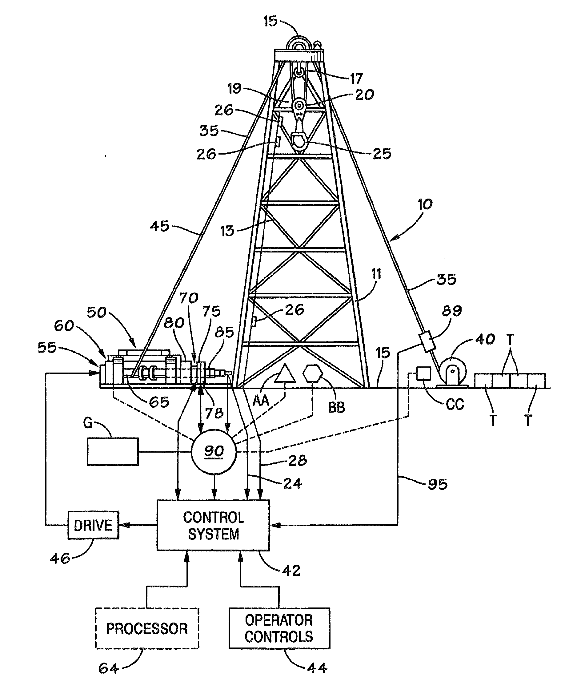
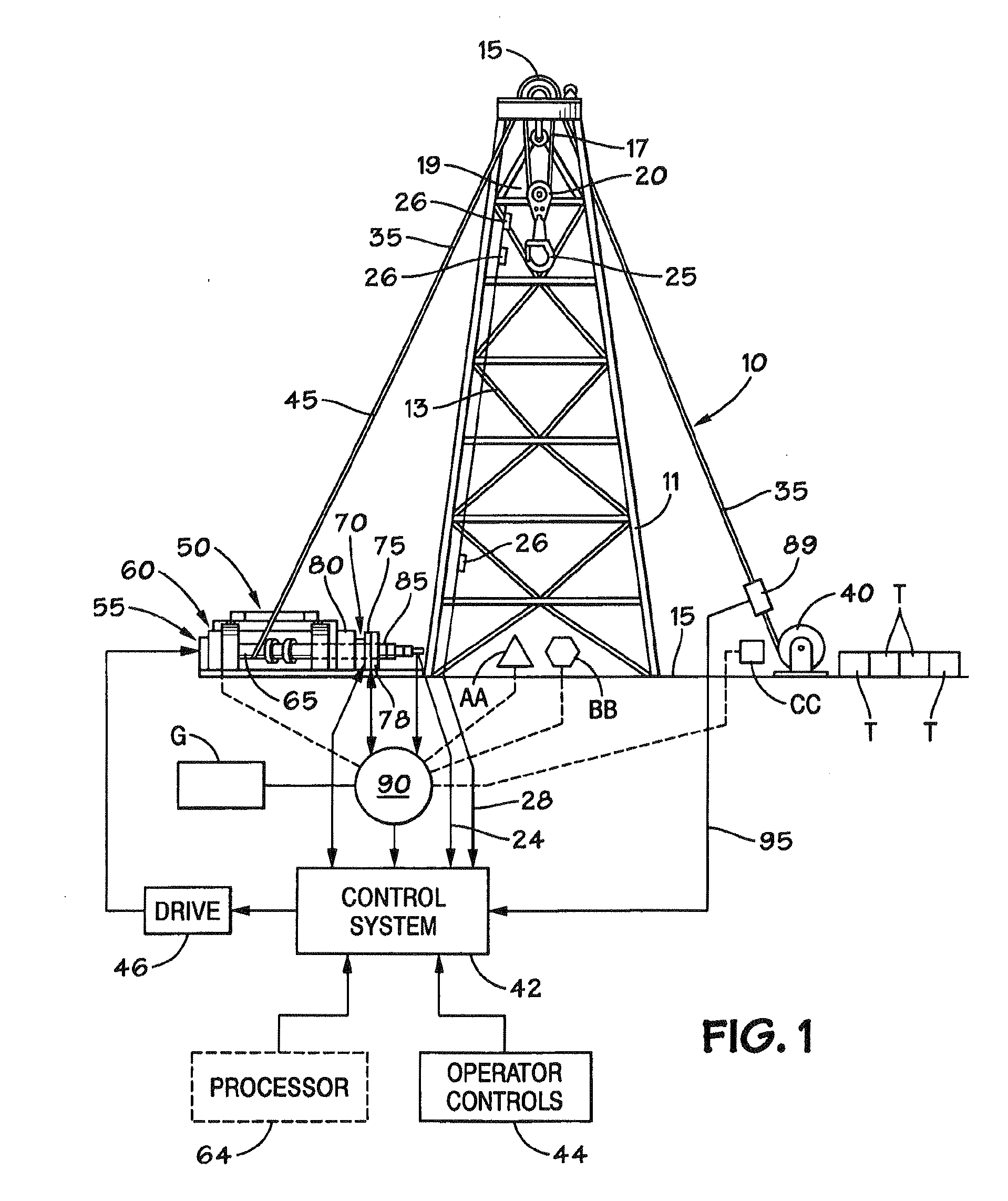
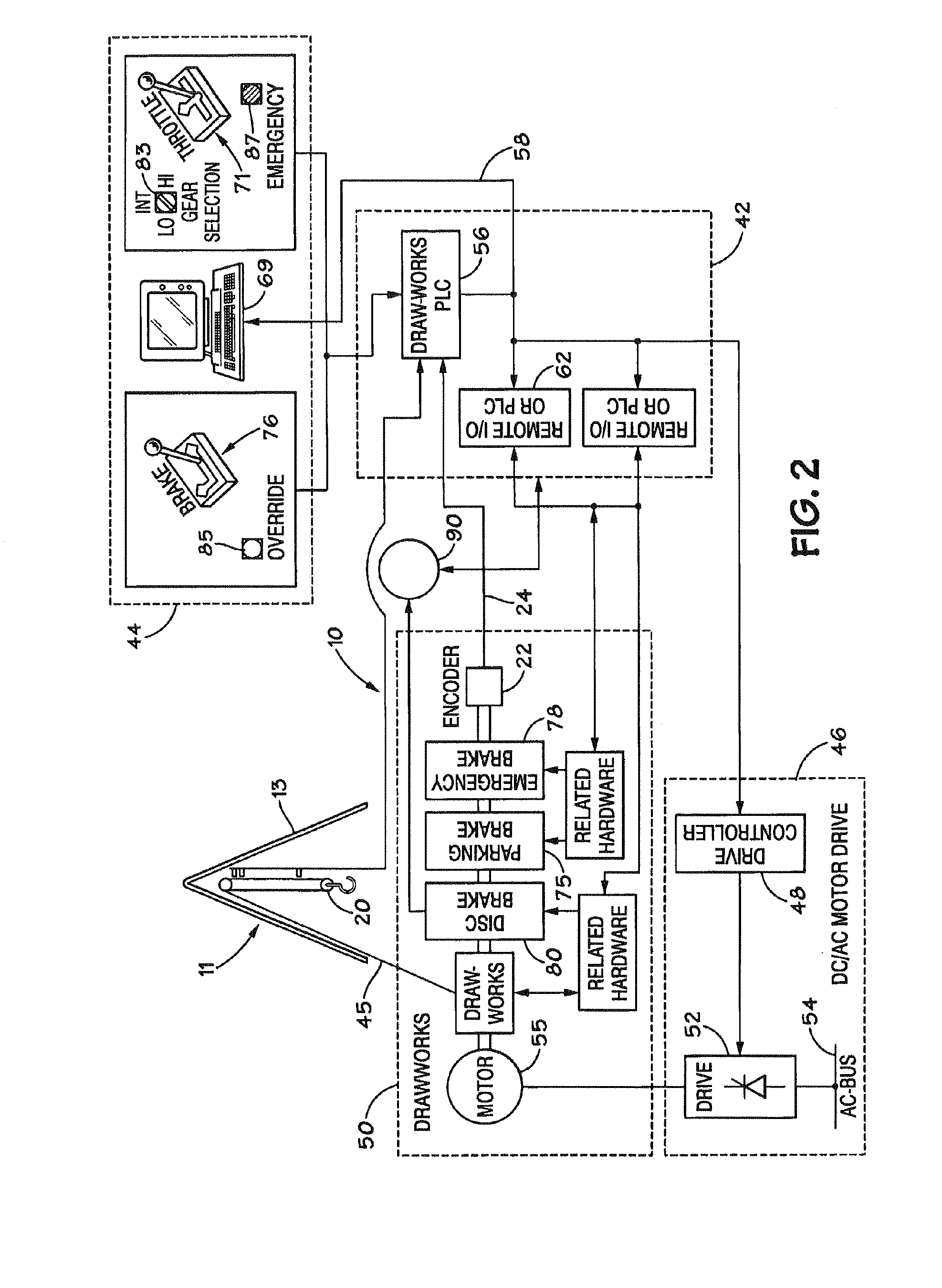
[0063]Referring to FIGS. 1 and 2, diagrams of a drawworks control system according to the present invention connected to a drilling rig and including a traveling block is illustrated. A system 10 according to the present invention has a derrick 11 that supports, at its upper end, a crown block 15. Suspended by a rope arrangement 17 from the crown block 15 is a traveling block 20, or load bearing part, for supporting a hook structure 25.

[0064]A hoisting line 30 is securely fixed at one end to ground by means of a dead line 35 and a dead line anchor 40. The other end of the hoisting line 30 forms a fast line 45 attached to drawworks 50. The drawworks 50 includes one or more electrical motors 55 and a transmission 60 connected to a cylindrical rotatable drum 65 for wrapping and unwrapping the fast line 45 as required for operation of the associated crown block 15 and traveling block 20. The rotatable drum 65 is also referred to as a winding drum or a hoisting drum. A brake arrangement ...


PUM


Abstract

A system for controlling power load to a rig engine of a wellbore rig. The system includes a controller for controlling the rig engine, a sensor for sensing the exhaust temperature of the rig engine, the sensor in communication with the controller for providing to the controller signals indicative of the exhaust temperature. The controller maintains the power load to the rig engine based on the exhaust temperature.

Description

[0001]This application is a divisional application of presently pending U.S. patent application Ser. No. 11 / 983,214, filed on Nov. 7, 2007, which application claims priority from U.S. Provisional Application Ser. No. 60 / 902,725, filed Feb. 22, 2007, both co-owned with the present invention and incorporated herein in its entirety for all purposes.BACKGROUND OF THE INVENTION[0002]1. Field of the Invention[0003]The present invention is directed, in certain aspects, to controlling generator engines, and in certain particular aspects, to controlling wellbore rig generator engines to control gas emissions that form; and in other aspects to power systems for rigs used in wellbore operations, e.g. drilling; to methods and systems and methods for recovering and using power generated by rig apparatuses; and to enhancing the quality of power used on a rig.[0004]2. Description of the Related Art[0005]Rigs used for wellbore operations, both land based and offshore, use a wide variety of tools, a...

Claims


Application Information

Patent Timeline
Patent Type & Authority Applications(United States)
IPC IPC(8): H02P9/04F03B15/00H02J3/06
CPCE21B3/02E21B19/08F02D2250/18F02D41/1497F02D41/1446E21B19/084
Inventor GRIMES, MARK FRANCISCERVENKA, GREGORY PAULHULICK, KENT
Owner VARCO I P INC
Learn More