Wellbore rig generator engine power control

Inactive Publication Date: 2008-08-28
VARCO I P INC
View PDF48 Cites 119 Cited by
  • Summary
  • Abstract
  • Description
  • Claims
  • Application Information

AI Technical Summary

Benefits of technology

[0019]The present invention, in certain aspects, discloses a power system for generator engines which manages power supplied to the engines and stores power to render engine operation more efficient; in some aspects, to improve or optimize engine l

Problems solved by technology

Such engines can be sluggish to respond to different power demands and this can negatively affect operations, e.g., but not limited to, tripping speeds.
In many instances, a variety of wellbore operations are intermittent and it is difficult and/or expensive to maintain such engines at a constant heavy loading.
The higher fuel consumption can result in excessive carbon dioxide emissions.
In many drilling applications, engines are inefficiently employed in order to compensate for transient loading on the generators, which is often a result of drawworks operation.
In natural gas powered systems, the throttle response under drawworks loading can be so sluggish it affects industry standard operational speeds.
This method of load leveling the engines consumes excessive fuel while the rig operating the drawworks, which produces higher volummes of carbon dioxide and NOx than are necessary.
In certain cases the power supplied to rig machines is of low quality (e.g., but not limited to, power which does not meet the standards of IEEE Standard 519).
The use of this low quality power is undesirable in certain situations and unsuitable for certain critical application, e.g. to run certain instruments, apparatuses, electrical components, sensitive electronic equipment, and computerized devices which can be damaged by low quality power, e.g. such low quality power can cause overheating or can cause standard equipment (e.g. transformers, motors, relays, resistors) to unnecessarily “trip” or activate causing equipment to go off line or causing erroneous signals.
In one particular aspect low quality power trip (unnecessarily) a relay that recognizes power drops.
Certain low quality power has high

Method used


Image

  • Wellbore rig generator engine power control
  • Wellbore rig generator engine power control
  • Wellbore rig generator engine power control

Examples


Example

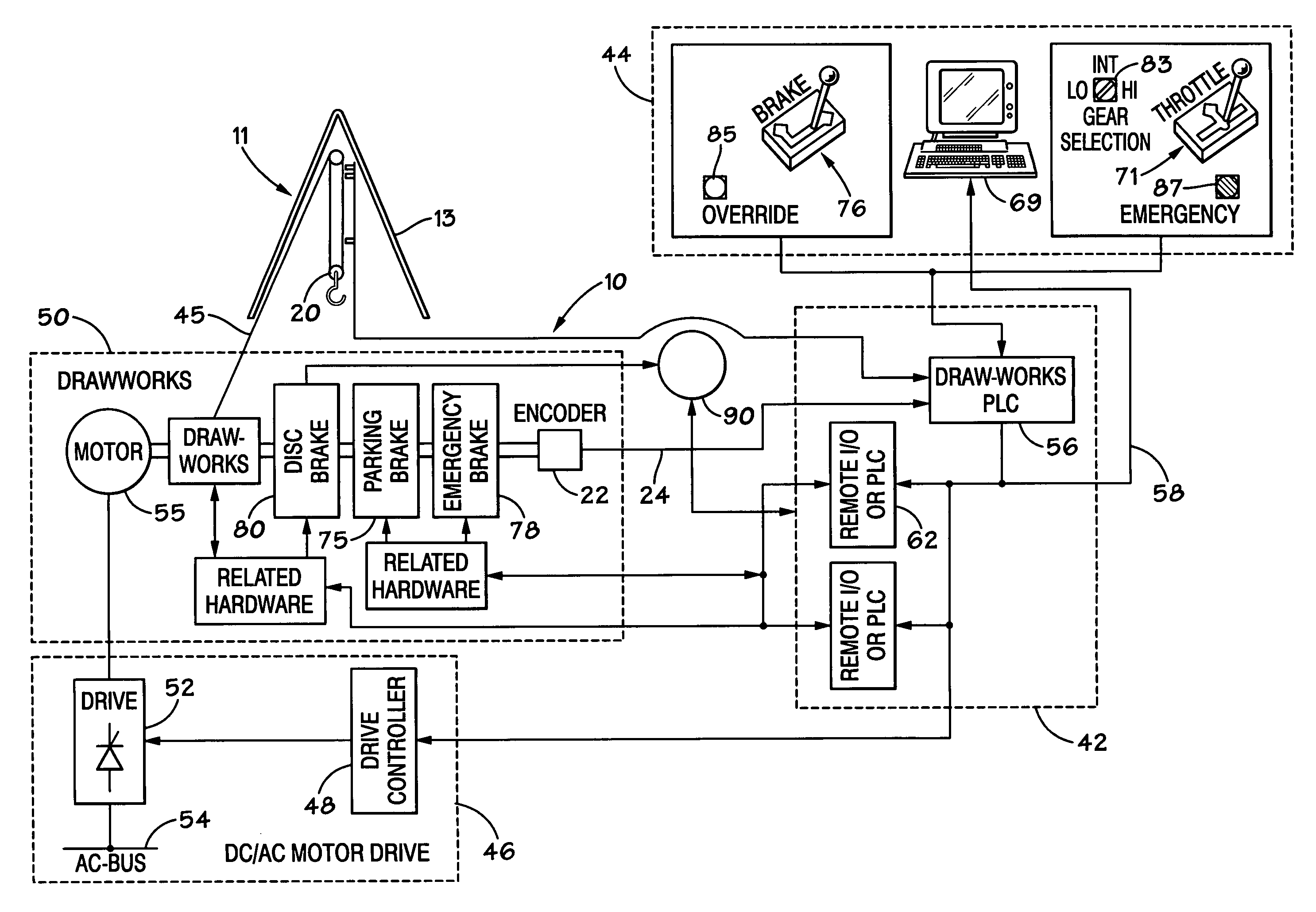
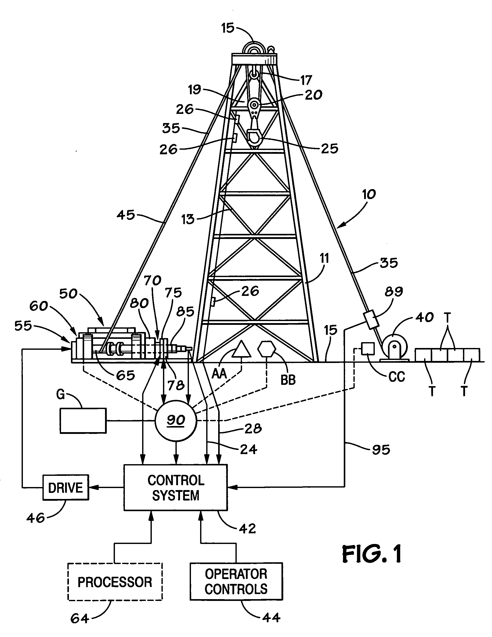
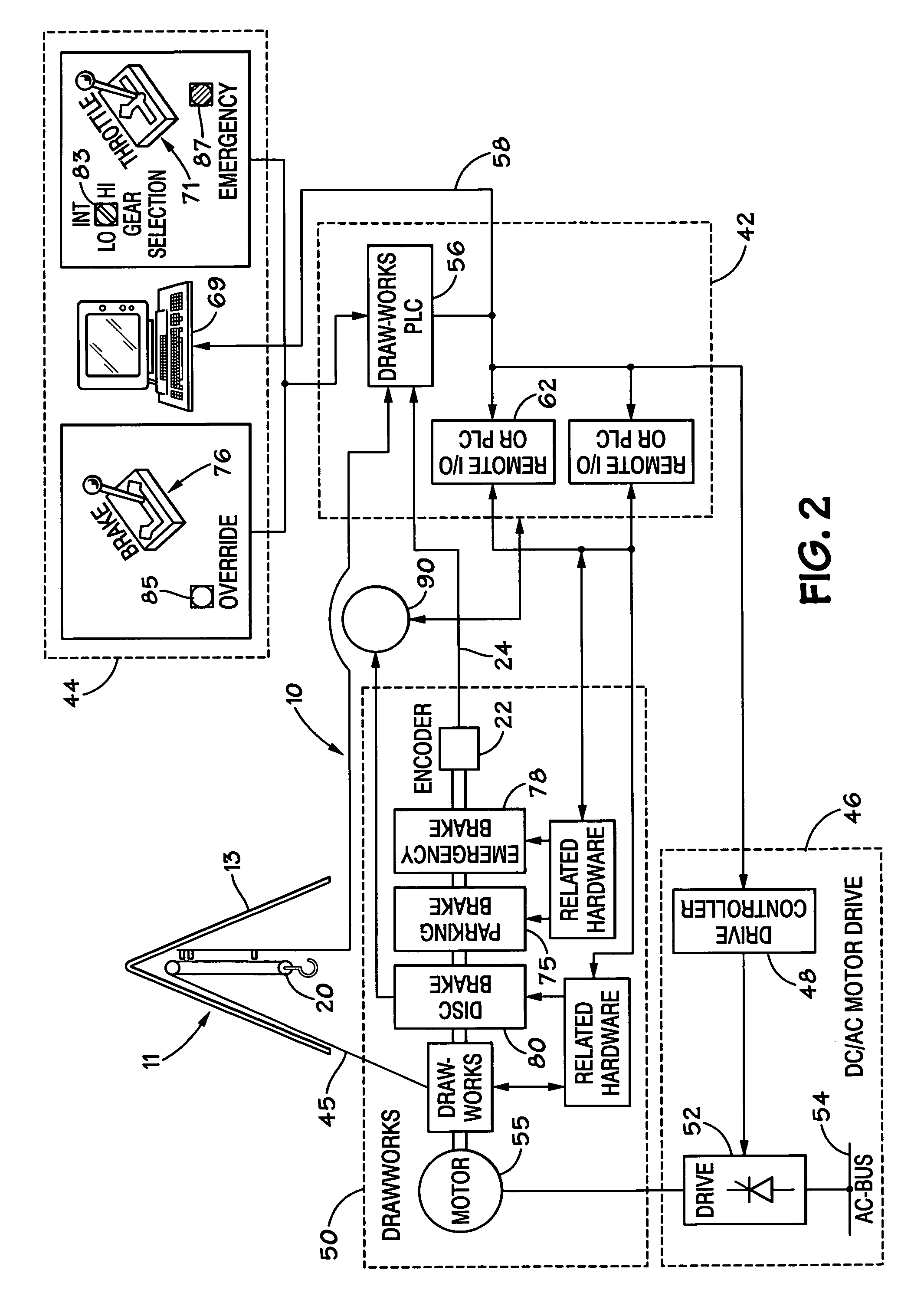
[0062]Presently preferred embodiments of the invention are shown in the above-identified figures and described in detail below. It should be understood that the appended drawings and description herein are of preferred embodiments and are not intended to limit the invention or the appended claims. On the contrary, the intention is to cover all modifications, equivalents and alternatives falling within the spirit and scope of the invention as defined by the appended claims. In showing and describing the preferred embodiments, like or identical reference numerals are used to identify common or similar elements. The figures are not necessarily to scale and certain features and certain views of the figures may be shown exaggerated in scale or in schematic in the interest of clarity and conciseness.

[0063]As used herein and throughout all the various portions (and headings) of this patent, the terms “invention”, “present invention” and variations thereof mean one or more embodiment, and a...


PUM


Abstract

A system for controlling power load to a rig engine of a wellbore rig, the system including a controller for controlling a rig engine, a sensor for sensing the exhaust temperature of a rig engine, the sensor in communication with the controller for providing to the controller signals indicative of the exhaust temperature, and the controller maintaining power load to the rig engine based on said exhaust temperature. This abstract is provided to comply with the rules requiring an abstract which will allow a searcher or other reader to quickly ascertain the subject matter of the technical disclosure. It is submitted with the understanding that it will not be used to interpret or limit the scope or meaning of the claims, 37 CFR 1.72(b).

Description

CROSS-REFERENCE TO RELATED APPLICATIONS[0001]The present invention and application claim priority under the Patent Laws based on U.S. Application Ser. No. 60 / 902,725 filed Feb. 22, 2007 co-owned with the present invention and incorporated herein in its entirety for all purposes.BACKGROUND OF THE INVENTION[0002]1. Field Of The Invention[0003]The present invention is directed, in certain aspects, to controlling generator engines, and in certain particular aspects, to controlling wellbore rig generator engines to control gas emissions that form; and in other aspects to power systems for rigs used in wellbore operations, e.g. drilling; to methods and systems and methods for recovering and using power generated by rig apparatuses; and to enhancing the quality of power used on a rig.[0004]2. Description of Related Art[0005]Rigs used for wellbore operations, both land based and offshore, use a wide variety of tools, apparatuses, appliances, systems and devices that use electrical power. Ty...

Claims


Application Information

Patent Timeline
IPC IPC(8): H02P9/04G06F19/00
CPCE21B3/02E21B19/08F02D2250/18F02D41/1497F02D41/1446E21B19/084
Inventor GRIMES, MARK FRANCISCERVENKA, GREGORY PAULHULICK, KENT
Owner VARCO I P INC
Why Eureka
Try Eureka