Piping, header, and tubing arrangements for solar boilers
What is Al technical title?
Al technical title is built by PatSnap Al team. It summarizes the technical point description of the patent document.
a solar boiler and solar energy technology, applied in the field of solar power production, can solve the problems of high heat transfer rate, new challenges in handling intense solar heat, and high pressure and temperature in the boiler tubing and related structures,
Inactive Publication Date: 2011-04-07
BABCOCK POWER SERVICES
View PDF111 Cites 9 Cited by
Summary
Abstract
Description
Claims
Application Information
AI Technical Summary
This helps you quickly interpret patents by identifying the three key elements:
Problems solved by technology
Method used
Benefits of technology
Problems solved by technology
This development has lead to new challenges in handling the intense solar heat without damage to the system.
This high heat transfer rate intensifies problems related to maintaining even heating and flow distribution throughout known designs of boiler panels.
The high heat transfer rate gives rise to high pressures and temperatures in the boiler tubing and related structures.
In the event of failure of one or more of the pumps, the functioning pump or pumps draw uneven amounts of water from the drum through the different downcomers, creating an unbalance of flow in the drum.
Unbalance along the length of the drum can lead to varying drum water level along the length of the drum.
Uneven water level in the drum can cause many problems including high carry-under (when saturated fluid enters the downcomers) to a false low water level alarm or low water level trip.
Prolonged operation with large unbalances in drum water level can also lead to constant water level alarms, water level trips, long-term fatigue and metallurgical problems from overheating, and affect the life and performance of the circulation pump.
This header arrangement, when applied to solar boiler applications, can lead to uneven flow from panel to panel, which can give rise to panel failure due to the intense heating described above.
This, together with the with the circulation header arrangement described above, can result in detrimental uneven flow throughout the boiler system, and causes a risk of emergency shutdown or even failure of key components.
Method used
Image
Click on the blue label to locate the original text in one second.
Reading with bidirectional positioning of images and text.
Examples
Embodiment Construction
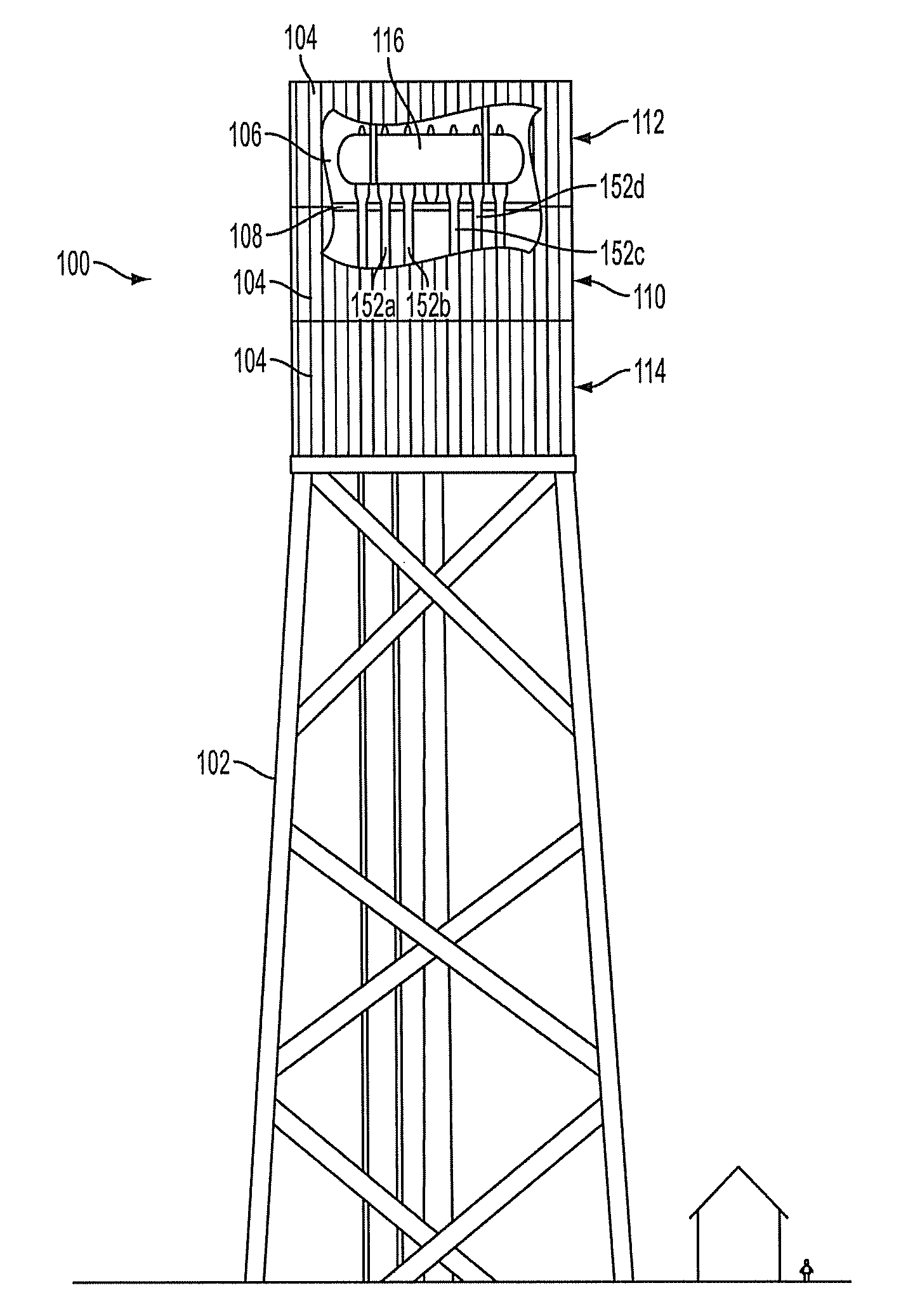
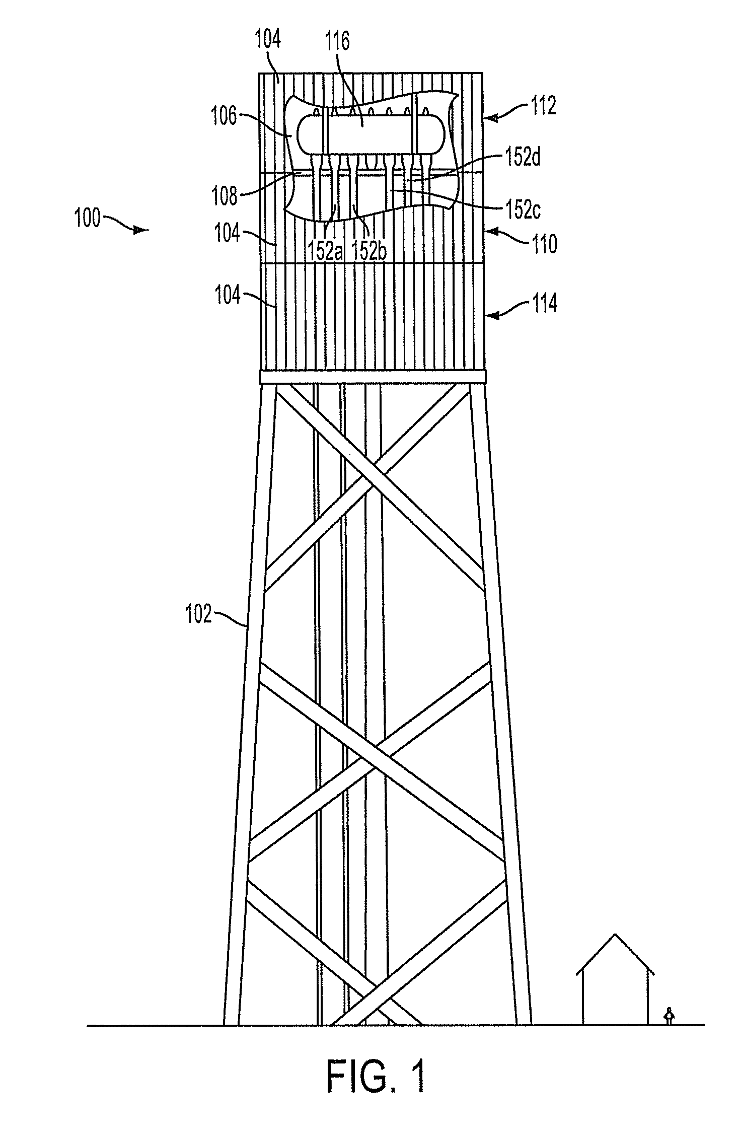
[0026]Reference will now be made to the drawings wherein like reference numerals identify similar structural features or aspects of the subject invention. For purposes of explanation and illustration, and not limitation, a partial view of an exemplary embodiment of a solar boiler in accordance with the invention is shown in FIG. 1 and is designated generally by reference character 100. Other embodiments of solar boilers in accordance with the invention, or aspects thereof, are provided in FIGS. 3-5, as will be described. The systems of the invention can be used improve circulation reliability and flow distribution within boilers, and particularly in solar boilers.
[0027]With reference now to FIG. 1, solar boiler 100 for solar power production is shown at the top of a solar receiver tower 102, which can be surrounded by a field of heliostats for focusing solar radiation on solar boiler 100. Solar boiler 100 includes a plurality of solar boiler panels 104 forming a perimeter surroundin...
PUM
Abstract
A header system for fluid circulation in a boiler includes a header configured to conduct fluid therethrough for circulating fluids in a boiler. A plurality of suction lines are connected in fluid communication with the header. Each suction line is configured and adapted to connect a respective pump in fluid communication with the header. A plurality of downcomers are connected in fluid communication with the header. Each downcomer is configured and adapted to connect the header in fluid communication with a steam drum. The header, suction lines, and downcomers are configured and adapted to draw substantially equal amounts of fluid from each of the downcomers even when flow is uneven among the suction lines. A plurality of cascaded headers can fluidly connect the circulation header to a steam generator. The plurality of cascaded headers is configured and adapted to provide a substantially equal flow to panels of the steam generator.
Description
CROSS-REFERENCE TO RELATED APPLICATIONS[0001]This application is a continuation in part of U.S. patent application Ser. No. 12 / 547, 650, filed Aug. 26, 2009. This application is also a continuation in part of U.S. patent application Ser. No. 12 / 620,109, filed Nov. 17, 2009. U.S. patent application Ser. Nos. 12 / 547,650 and 12 / 620,109 each claim priority to U.S. Provisional Application No. 61 / 151,984, filed Feb. 12, 2009, to U.S. Provisional Application No. 61 / 152,011, filed Feb. 12, 2009, to U.S. Provisional Application No. 61 / 152,035, filed Feb. 12, 2009, to U.S. Provisional Application No. 61 / 152,049, filed Feb. 12, 2009, to U.S. Provisional Application No. 61 / 152,077, filed Feb. 12, 2009, to U.S. Provisional Application No. 61 / 152,114, filed Feb. 12, 2009, and to U.S. Provisional Application No. 61 / 152,286, filed Feb. 13, 2009. Each of the above-referenced applications is incorporated by reference herein in its entirety.BACKGROUND OF THE INVENTION[0002]1. Field of the Invention[00...
Claims
Application Information
Patent Timeline
Application Date:The date an application was filed.
Publication Date:The date a patent or application was officially published.
First Publication Date:The earliest publication date of a patent with the same application number.
Issue Date:Publication date of the patent grant document.
PCT Entry Date:The Entry date of PCT National Phase.
Estimated Expiry Date:The statutory expiry date of a patent right according to the Patent Law, and it is the longest term of protection that the patent right can achieve without the termination of the patent right due to other reasons(Term extension factor has been taken into account ).
Invalid Date:Actual expiry date is based on effective date or publication date of legal transaction data of invalid patent.
Patent Type & Authority Applications(United States)