Sealing for vane segments

Active Publication Date: 2011-04-07
PRATT & WHITNEY CANADA CORP
View PDF22 Cites 155 Cited by
  • Summary
  • Abstract
  • Description
  • Claims
  • Application Information

AI Technical Summary

Problems solved by technology

The circumferential gaps between the segments usually are sealed by feather seals, but may still be a source of cooling air leakage into th

Method used


Image

  • Sealing for vane segments
  • Sealing for vane segments
  • Sealing for vane segments

Examples


Embodiment Construction

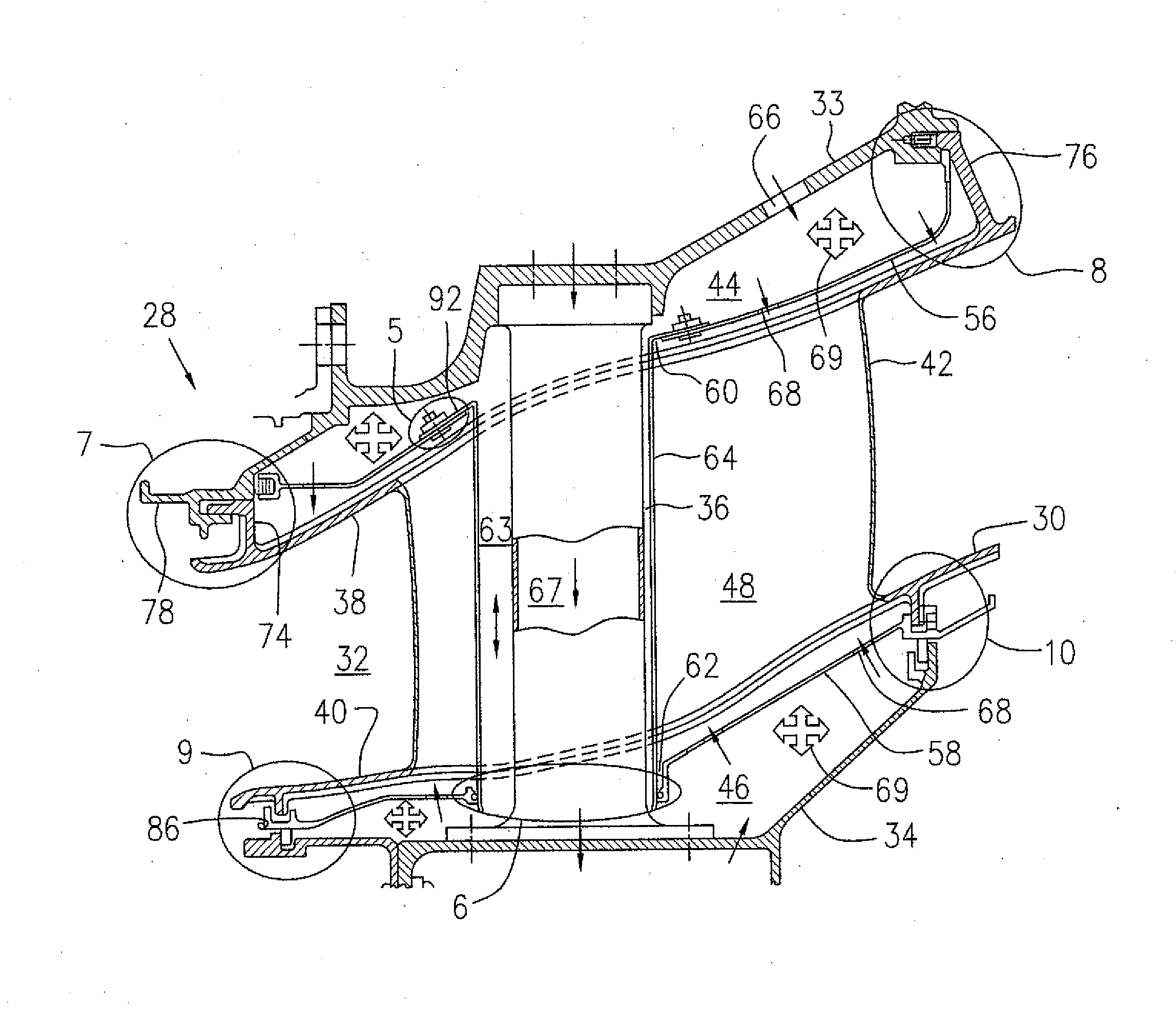
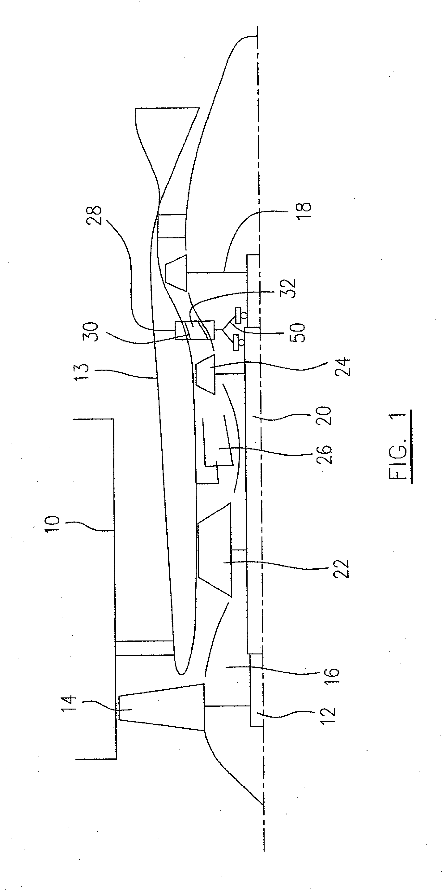
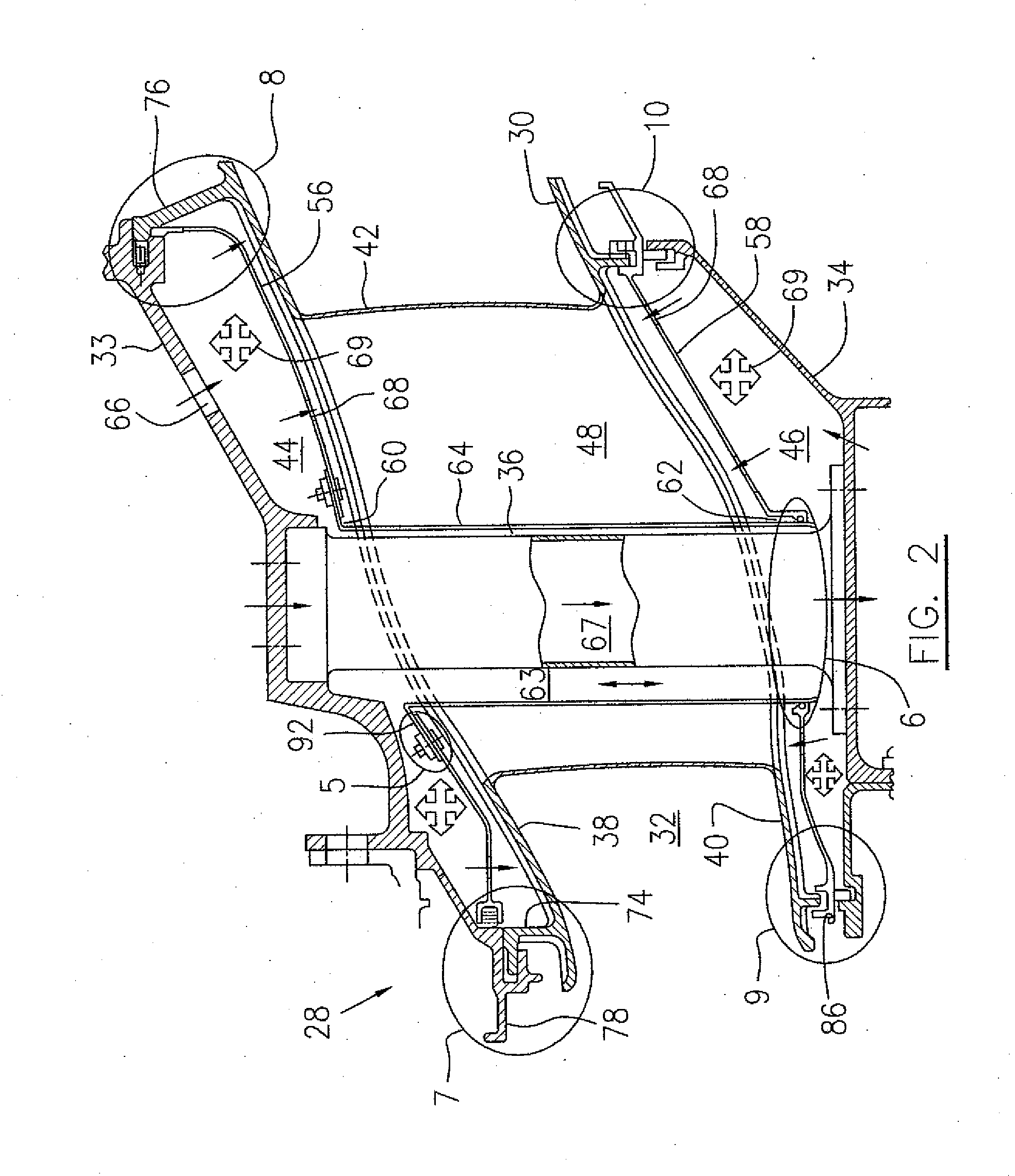
[0020]Referring to FIG. 1, a bypass gas turbine engine includes a fan case 10, a core casing 13, a low pressure spool assembly which includes a fan assembly 14, a low pressure compressor assembly 16 and a low pressure turbine assembly 18 connected by a shaft 12 and a high pressure spool assembly which includes a high pressure compressor assembly 22 and a high pressure turbine assembly 24 connected by a turbine shaft 20. The core casing 13 surrounds the low and high pressure spool assemblies to define a main fluid path therethrough. In the main fluid path there is provided a combustor 26 which generates combustion gases to power the high pressure turbine assembly 24 and the low pressure turbine assembly 18. A mid turbine frame (MTF) 28 is provided between the high pressure turbine assembly 24 and the low pressure turbine assembly 16 and includes a bearing housing 50 to support bearings around the respective shafts 20 and 12. The mid turbine frame 28 includes an inter-turbine duct (IT...


PUM


Abstract

A seal housing is provided to substantially cover at least one duct wall of vane array duct of a gas turbine engine, and one example arrangement is employed in a mid-turbine frame. The arrangement provides improved sealing of the vane array duct through the provision of a plurality of cavities extending along the duct wall. The arrangement may also include insulation tubes to assist in sealing around load transfer spokes passing through the vane array.

Description

TECHNICAL FIELD[0001]The described subject matter relates generally to gas turbine engines and more particularly, to an arrangement for vane segments of gas turbine engines.BACKGROUND OF THE ART[0002]A gas turbine engine includes typically a segmented vane ring configured with outer and inner annular duct walls connected by a plurality of airfoils. The circumferential gaps between the segments usually are sealed by feather seals, but may still be a source of cooling air leakage into the hot gas path and / or hot gas ingestion from the hot gas path, if these circumferential gaps between the segments are not adequately sealed. Thus, there is room for improvement.[0003]Accordingly, there is a need to provide an improved vane arrangement.SUMMARY[0004]In one aspect, the described subject matter provides a gas turbine engine comprising a segmented vane array disposed radially between annular outer and inner engine cases and including a segmented annular outer duct wall, a segmented annular ...

Claims


Application Information

Patent Timeline
IPC IPC(8): F01D11/08
CPCF01D9/06F01D25/12F01D11/00
Inventor DUROCHER, ERICPIETROBON, JOHN
Owner PRATT & WHITNEY CANADA CORP
Why Eureka
Try Eureka