Twist Drill

a drill point and drill bit technology, applied in the field of drill points, can solve the problems of more difficult drilling of the drill point to pierce the workpiece and centering the drill poin

Active Publication Date: 2011-04-14
ISCAR LTD
View PDF11 Cites 17 Cited by
  • Summary
  • Abstract
  • Description
  • Claims
  • Application Information

AI Technical Summary

Problems solved by technology

Drills having a generally sharper drill point design will generally penetrate the workpiece more easily but in most cases that may be at the expense of a more fragile dril

Method used


Image

  • Twist Drill
  • Twist Drill
  • Twist Drill

Examples


Embodiment Construction

[0019]In the following description, various aspects of the present invention will be described. For purposes of explanation, specific configurations and details are set forth in order to provide a thorough understanding of the present invention. However, it will also be apparent to one skilled in the art that the present invention may be practiced without the specific details presented herein. Furthermore, well-known features may be omitted or simplified in order not to obscure the present invention.

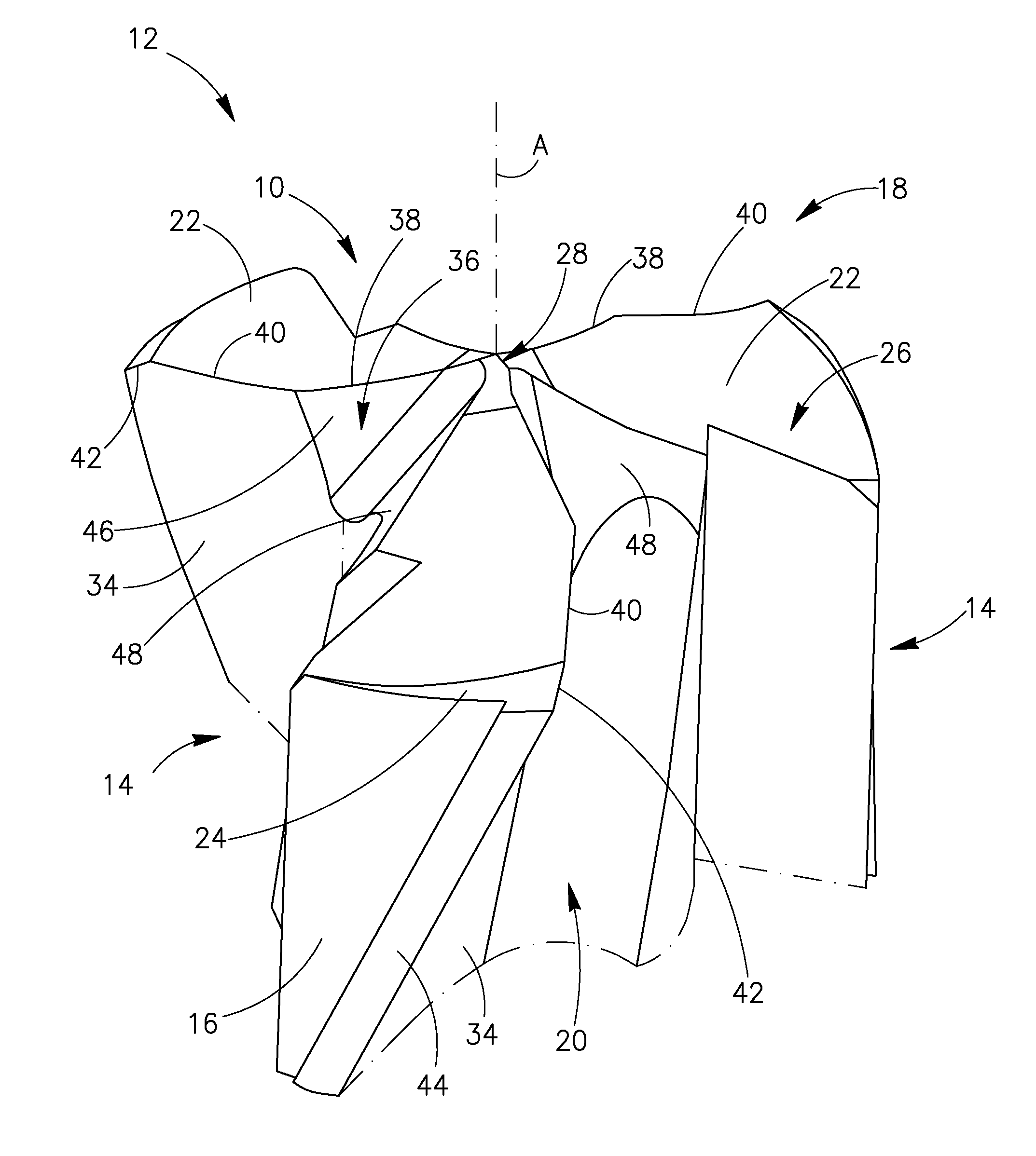
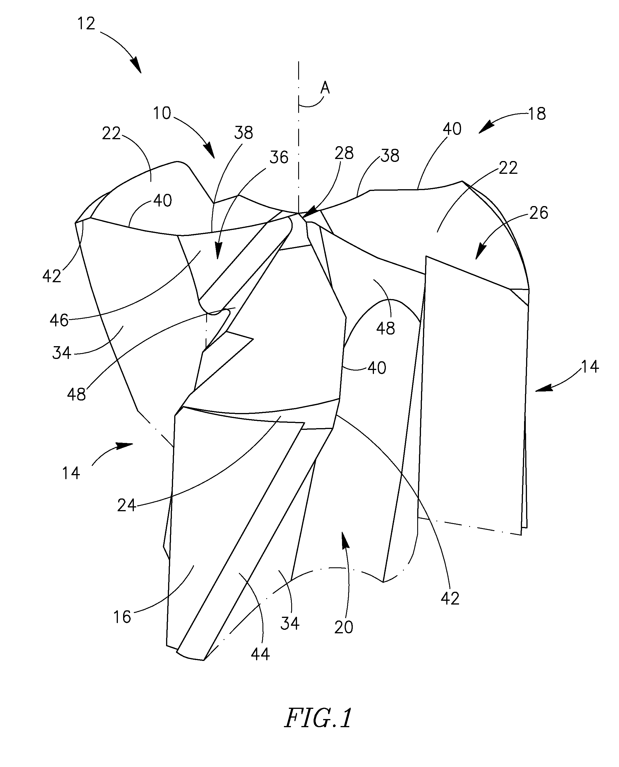
[0020]Reference is made to the figures in general and specifically to FIG. 1, showing a partial isometric view of a cutting portion 10 at a front end of a twist drill 12 having an axis of rotation A and a diameter D, in accordance with embodiments of the invention. The twist drill 12 has a cylindrical drill body 14 and has a peripheral surface 16. The cutting portion 10 may be part of a one-piece drill or a part of a replaceable cutting head and may be comprised of solid carbide. In acco...


PUM

PropertyMeasurementUnit
Angleaaaaaaaaaa
Angleaaaaaaaaaa
Angleaaaaaaaaaa

Abstract

A twist drill includes a cutting portion and a drill body. The cutting portion has a chisel edge, a segment relief surface, a chamfer relief surface and at least two flutes extending longitudinally to the drill body. Each flute has a rake surface and a gash extending away from the chisel edge. The cutting portion further has at least two cutting segments, each cutting segment having a first curved cutting edge, a second curved cutting edge and a chamfer cutting edge.

Description

FIELD OF THE INVENTION[0001]The present invention relates to twist drills having shaped cutting edges.BACKGROUND OF THE INVENTION[0002]Self centering of a drill may be achieved by utilizing a known principle: minimizing a tangent angle, near the chisel edge, formed between a tangent to a cutting edge and an axis of rotation of the drill. Many different approaches have been taken in order to achieve optimal drill point geometry. The design of the cutting edges in general and near the chisel edge in particular is usually a tradeoff between toughness of the drill point and the ability to penetrate the workpiece efficiently. Drills having a generally sharper drill point design will generally penetrate the workpiece more easily but in most cases that may be at the expense of a more fragile drill point. A more robust, wider design of the drill point will make it sturdier but it may be more difficult for the drill point to pierce the workpiece and center the drill. An important aspect, dep...

Claims


Application Information

Patent Timeline
IPC IPC(8): B23B51/02
CPCB23B51/02B23B2251/082B23B2251/14Y10T408/9097B23B2251/202Y10T408/9095Y10T408/905B23B2251/18B23B2251/122
Inventor HAROUCHE, DAVID BEN
Owner ISCAR LTD
Why Eureka
Try Eureka