Method and apparatus for airway compensation control

a compensation control and airway technology, applied in the field of mechanical ventilation, can solve the problems of inability to provide an indication, inability to provide a method or system, and inability to complete the pneumatic seal, etc., and achieve the effect of measuring the resistance of the endotracheal tub

Active Publication Date: 2011-04-14
GENERAL ELECTRIC CO
View PDF13 Cites 50 Cited by
  • Summary
  • Abstract
  • Description
  • Claims
  • Application Information

AI Technical Summary

Problems solved by technology

These difficulties may be pathological in nature or may be due to the fact that the patient is too weak or sedated to independently perform respiration functions.
Ventilation masks are the most simple to attach to the patient; however, these masks tend to form an incomplete pneumatic seal with the patient's airway.
While the use of an endotracheal tube allows for the very careful management of patient respiration, there are limitations associated with the use of endotracheal tubes that are counterproductive to the careful management of patient respiration.
Currently, there is no method or system for providing an indication of whether there is mucus buildup in the endotracheal tube.
However, the type of flow is difficult to directly monitor.
Further, the build-up of mucus within the endotracheal tube reduces the effective diameter of the tube.
This limits the accuracy of the airway resistance compensation for the resistance since for laminar flow the resistance is related to the fourth power of the diameter of the endotracheal tube, thus filtering the signals the patient actually receives.
Specifically, the current models of endotracheal tube resistance do not account for the common practice of a clinician cutting the tube to a shorter length to secure a proper fit within the trachea of the patient or for changes in the endotracheal tube resistance resulting from the buildup of mucus within the endotracheal tube.

Method used


Image

  • Method and apparatus for airway compensation control
  • Method and apparatus for airway compensation control
  • Method and apparatus for airway compensation control

Examples


Embodiment Construction

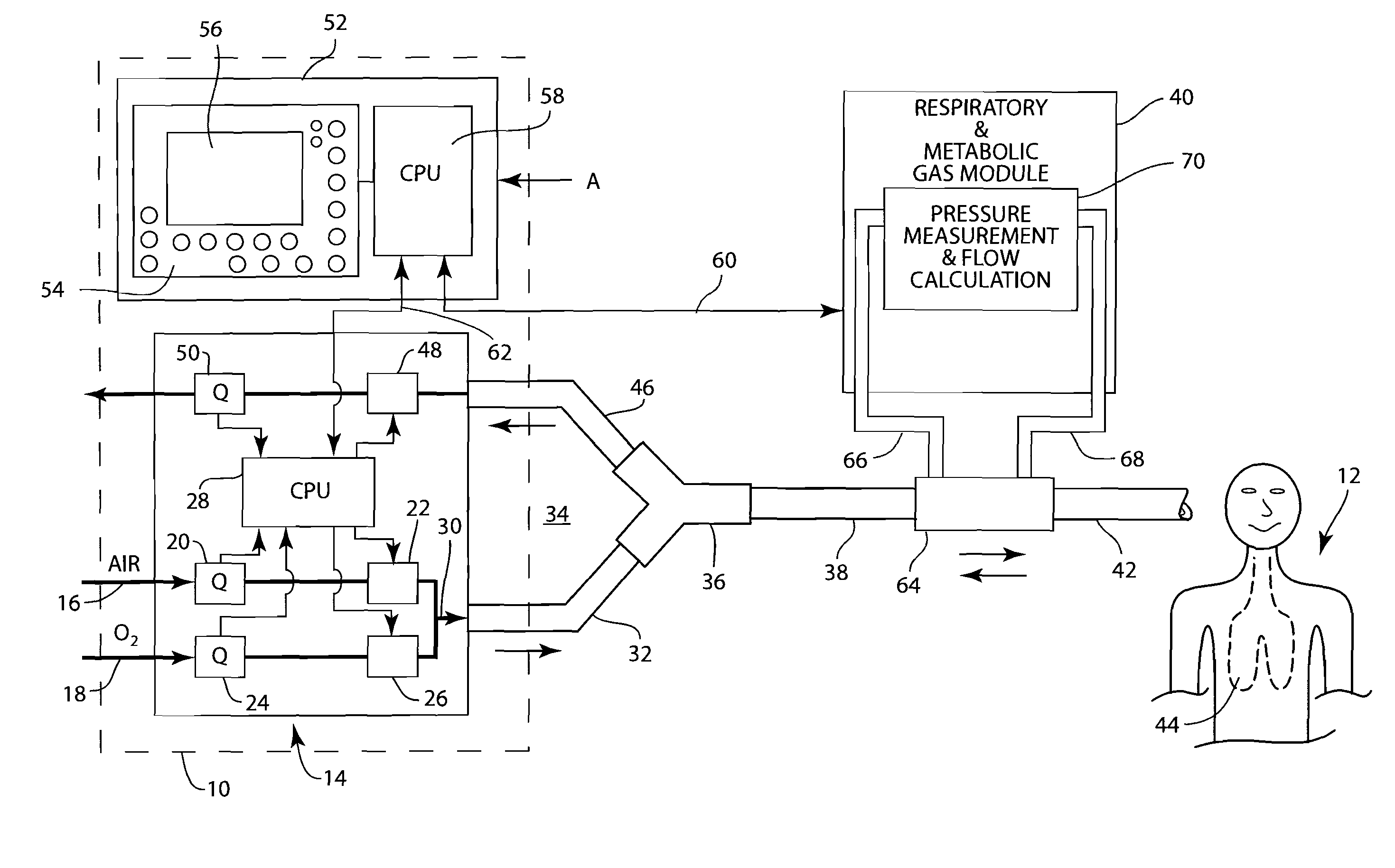
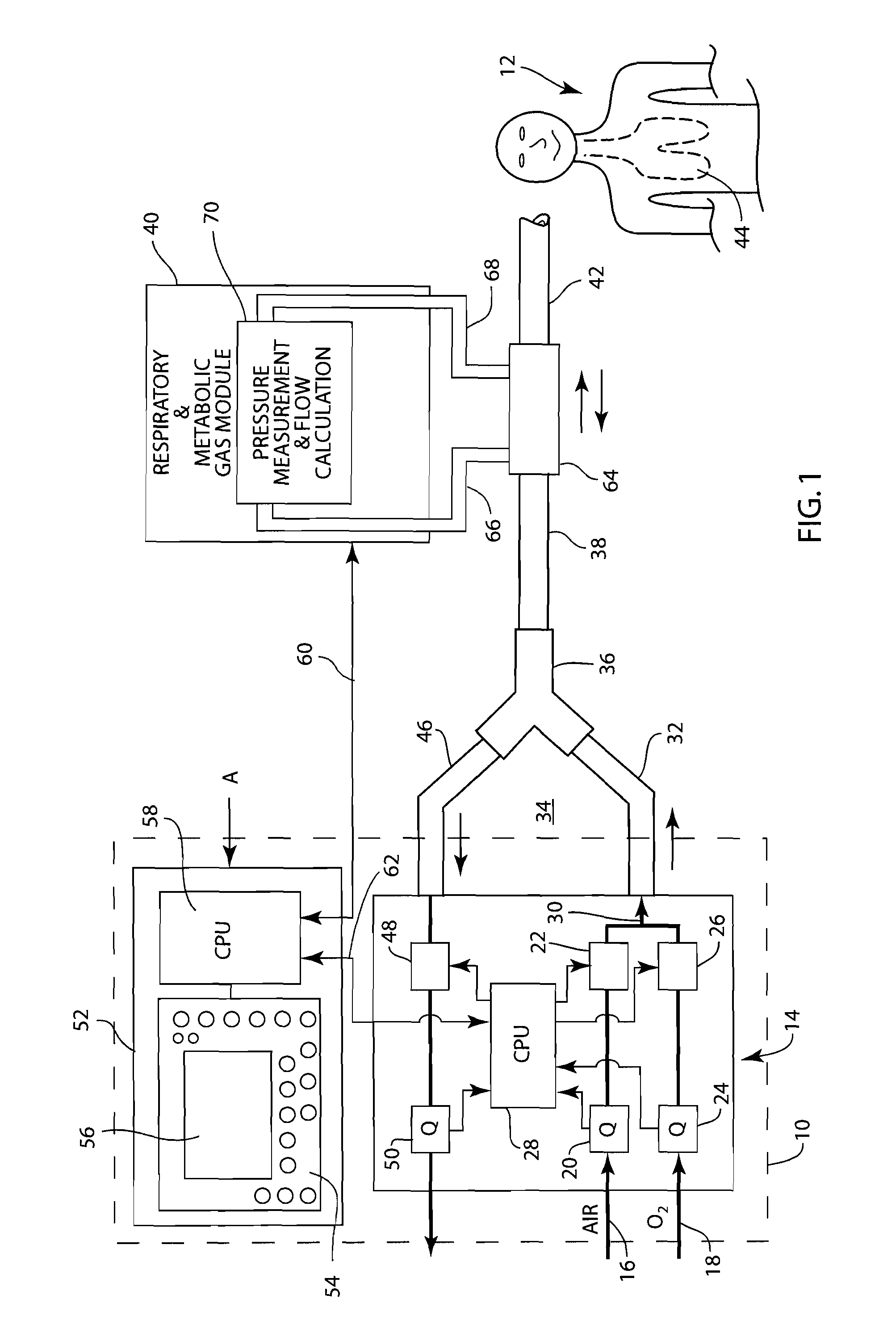
[0019]FIG. 1 depicts a schematic diagram of a mechanical ventilator system 10 set up according to an embodiment of the present invention to provide respiratory support to a patient 12. A ventilator system 10 comprises a mechanical ventilator 14 that performs the mechanical and pneumatic functions of the ventilator system 10 for providing respiratory support to the patient 12. The mechanical ventilator 14 receives medical gas in the form of air 16 but may also receive a supplemental gas such as oxygen 18. The air that is supplied to the patient 12 is regulated by a flow sensor 20 and a control valve 22. Similarly, the supplemental gas 18 is controlled by flow sensor 24 and control valve 26. A controller 28, which may comprise a microprocessor or a CPU, receives flow rates measured by the flow sensors 20 and 24 and controls the amounts of the medical gases 16 and 18 to be delivered to the patient 12 by regulating the control valves 22 and 26.

[0020]The term medical gas is used to refer...


PUM


Abstract

A method for controlling a mechanical ventilator that is supplying medical gas to a patient via an endotracheal tube. A pressure is measured from a patient end of an endotracheal tube. The pressure at the patient end of the endotracheal tube is used to create an improved endotracheal tube resistance model such that the medical gas supplied by the mechanical ventilator may be compensated for the resistance of the endotracheal tube thereby providing increased control over the medical gas that is delivered to the patient's lungs. Additionally, if an obstruction in the patient's airway is detected, the location of the obstruction may be targeted such that the proper remedial treatment or procedure is selected by a clinician.

Description

FIELD OF THE INVENTION[0001]The present invention relates to the field of mechanical ventilation for providing respiratory support to a patient. More specifically, the present invention relates to a method for determining the resistance of a patient connection and compensating the delivery of gases by the mechanical ventilator based upon the measured resistance.BACKGROUND OF THE INVENTION[0002]Patients that have respiratory difficulties often must be placed on a mechanical ventilator. These difficulties may be pathological in nature or may be due to the fact that the patient is too weak or sedated to independently perform respiration functions. A breath of medical gas is provided by the mechanical ventilator to the patient via a patient connection under a pressure that is sufficient to overcome the resistance of the patient's airway to fill the lungs. When the pressure of the medical gas is reduced, the natural compliance of the patient's lungs and chest wall forces the delivered br...

Claims


Application Information

Patent Timeline
Patent Type & Authority Applications(United States)
IPC IPC(8): A61M16/00A61B5/08
CPCA61M16/0051A61M16/12A61M2016/0027A61M2016/0036A61M2016/0039A61M16/0402A61M2016/103A61M2202/0208A61M2205/502A61M2230/432A61M2230/435A61M2016/1025A61M16/042A61M16/0833A61M16/0858A61M16/0866A61M16/024
Inventor CHONCHOLAS, GARY J.TOBIA, RONALD L.
Owner GENERAL ELECTRIC CO
Why Eureka
Try Eureka