Automatic syringes

a technology of automatic syringes and syringes, which is applied in the field of syringes, can solve the problems of inability to control, inability to provide control, and unstable syringes,

Inactive Publication Date: 2011-04-14
SIBBITT JR WILMER L +1
View PDF2 Cites 46 Cited by
  • Summary
  • Abstract
  • Description
  • Claims
  • Application Information

AI Technical Summary

Benefits of technology

[0026]The prior art does not describe an automatic syringe that can conveniently be held in a pencil grip, can both automatically aspirate and inject using mechanical mechanisms, is controlled by a finger-operated valve at the front of the syringe, and can use conventional luer fittings and attachments.
[0027]An example embodiment of this invention provides a multipurpose one-handed pencil-grip automatic syringe device that can both automatically aspirate and inject comprising a forwardly mounted finger controlled valve that operates the device, a largely conventional syringe barrel, a plunger modified to accommodate a spring within the syringe barrel, a means to retain the spring within the barrel, a spring biased to force the plunger into the syringe barrel to cause injection, a means to reversibly and mechanically engage the barrel to the plunger in order to lock the plunger to create vacuum and in order release the plunger so that the syringe only aspirates or injects when intended, and a device that can accommodate standard luer or luer lock fitting or with modification other fittings.
[0028]An example embodiment of this invention provides a multipurpose one-handed pencil-grip automatic syrin

Problems solved by technology

Of course, in this manual arrangement, the plunger of the syringe which is at the back section of syringe, cannot be operated to aspirate or inject without radically changing finger position, thus, the need for automatic syringes to aspirate or inject that are controlled by a mechanism at the forward section of the syringe.
This device does not have a valve, cannot automatically aspirate, cannot provide controlled injection, the plunger does not lock, and the syringe is unstable when filled with liquid (that is it automatically injects).
There is no anterior valve or other means to control outflow or inflow into the device.
U.S. Pat. No. 4,364,376 to Bigham describes a syringe with a valve (turncock or stopcock) but it is a double bolus syringe for injection, requires two hands to operate, and is not an automatic syringe.
However, the syringe is not held in the fingertips, and there is no finger-operated valve.
U.S. Pat. No. 4,755,172 and U.S. Pat. No. 4,863,429 to Baldwin describes an external housing that converts a syringe into automatic infusion device with an anteriorly biased on-off valve; however, this not a hand-held device, is bulky, is not intended for precise placement of medication, and cannot be used to aspirate.
U.S. Pat. No. 5,246,011 and U.S. Pat. No. 5,651,372 to Caillouette describe an aspiration syringe that has a ratchet mechanism or stop to control the plunger, but it has no valve connected to the needle, does not automatically inject, and cannot conveniently be held like a pencil.
These devices are “on” and “off”, and do not have any variable control as to vacuum, thus, they are not well-suited to fluid aspiration procedures where control of vacuum critical, and they are very expensive and complex, and they cannot be used to inject.
U.S. Pat. No. 4,236,516 to Nilson demonstrates a spring-driven automatic aspiration device, but there is no finger-controlled valve in at the proximal end of the syringe and this device cannot automatically inject.
U.S. Pat. No. 4,073,288 to Chapman also discloses a valve to control vacuum, but the valve is not situated at the front end of the syringe, and is a valve not easily manipulated by one finger.
US25101879A1 to Shidham et al. discloses an aspiration syringe with an anterior valve in the shape of a turn cock or stop cock that uses piston locks that snap onto the plunger to hold the plunger in place; however, this is not an injection automatic syr

Method used


Image

  • Automatic syringes
  • Automatic syringes
  • Automatic syringes

Examples


Embodiment Construction

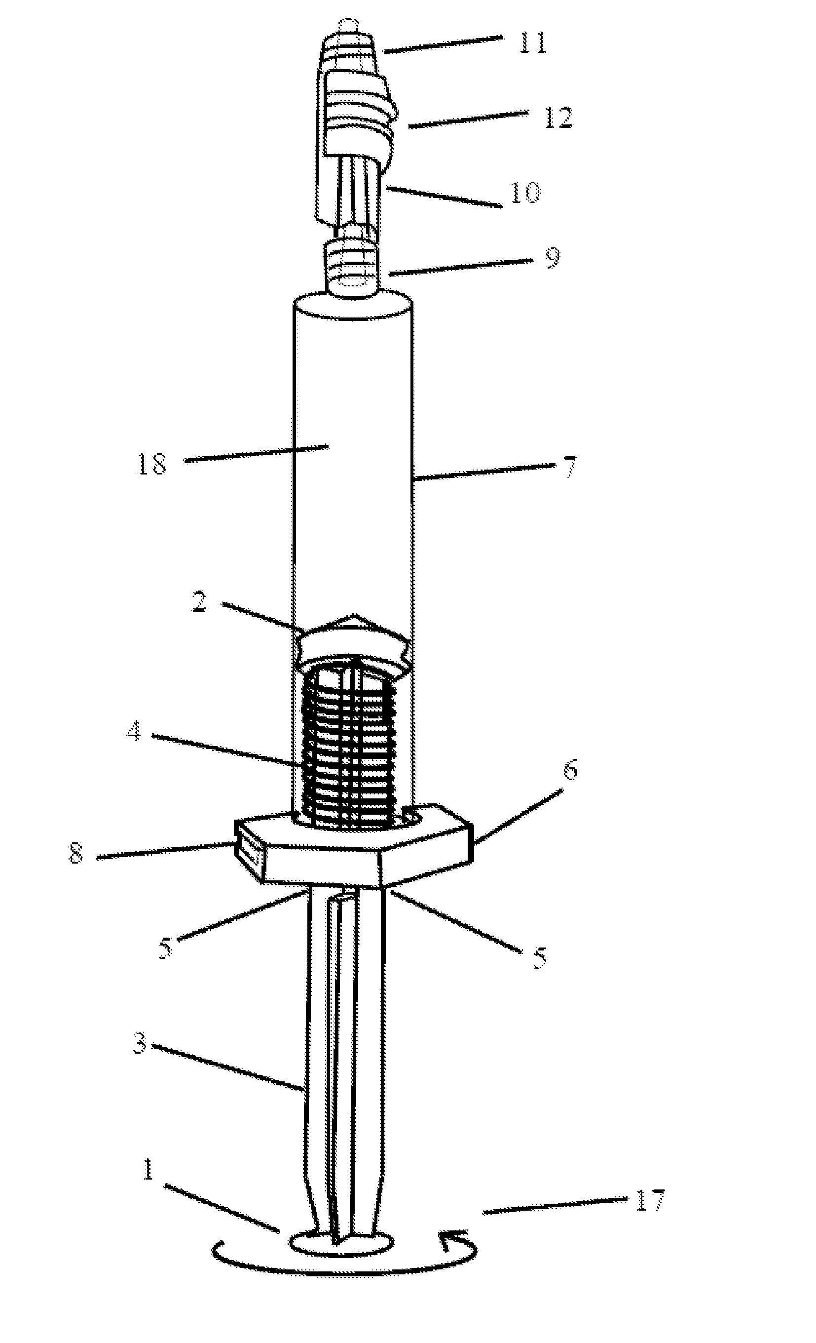
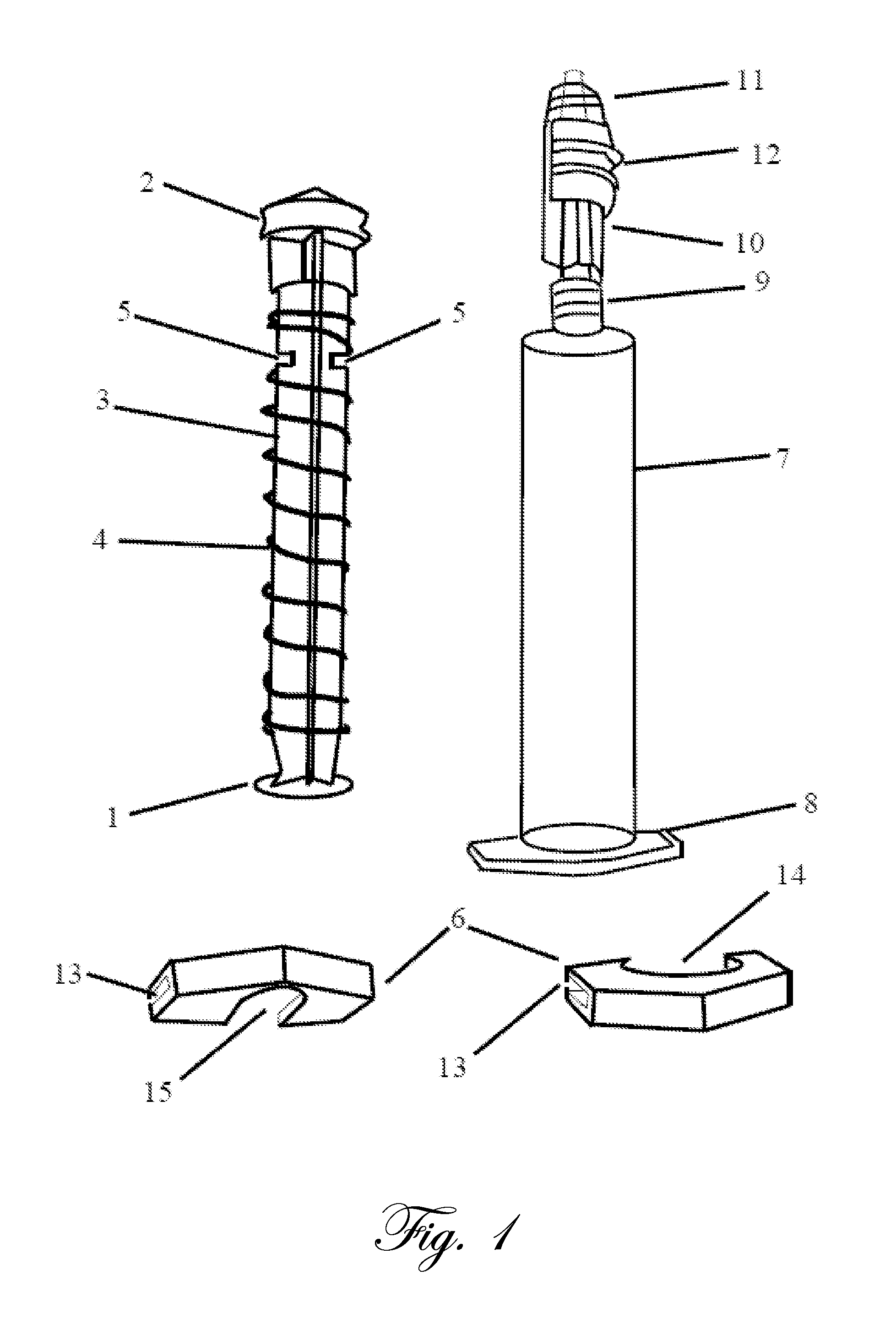
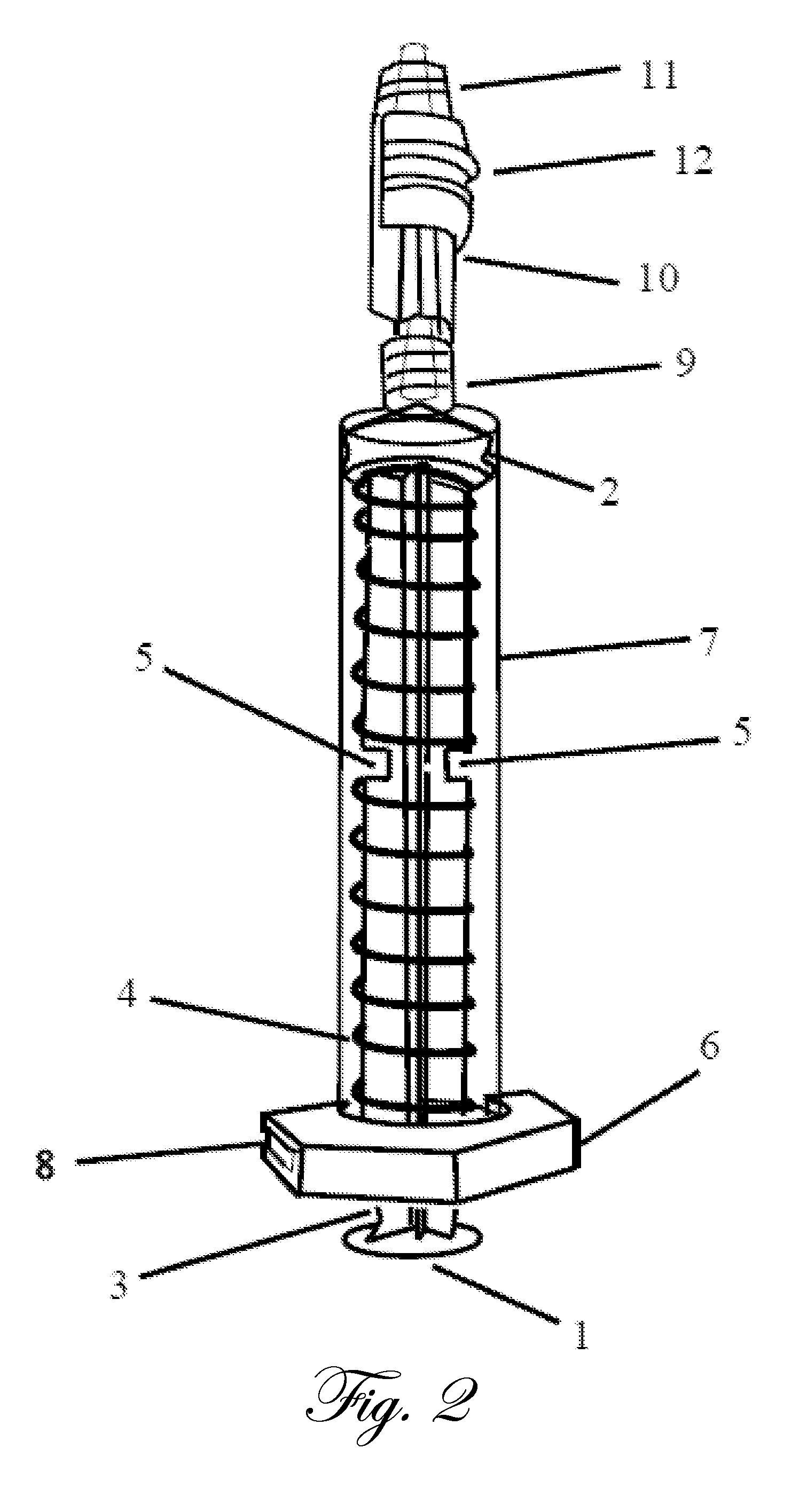
[0049]FIG. 1 is a schematic illustration of an example embodiment of an automatic syringe. FIG. 14 is a photograph of an example embodiment similar to that described in connection with FIG. 1. A plunger has a the thumb rest 1 (plunger flange), a the stopper or seal complex 2 of the plunger of a particular diameter, a plunger body 3 of a lesser diameter of the stopper or seal of the plunger, a spring 4 that encircles the plunger body and abuts on the seal complex that is of greater diameter than the spring, and notches 5 in the plunger that are the female component to the male component of a barrel endplate mechanism to reversibly lock the plunger in position. An endplate 6 of the barrel comprises a clip, fitting, or intrinsic molding of the barrel that is clipped, bonded, glued, welded or molded firmly to finger flanges 8 of the barrel 7 and contains and restrains the spring 4 within the syringe barrel 7 and reversibly mates with the notches 5 in the body of the plunger reversibly l...


PUM

PropertyMeasurementUnit
Fractionaaaaaaaaaa
Fractionaaaaaaaaaa
Fractionaaaaaaaaaa

Abstract

The present invention provides automatic syringes that can be held with one hand in a pencil-grip in which the fingers (thumb or index finger) operate a forwardly based valve that along with selection of needle diameter and length, control the ingress or egress of fluid from the automatic syringe. These finger-controlled one-handed automatic syringes can be used in image-directed procedures such as ultrasound (sonography)-directed procedures in which the ultrasound probe is controlled with one hand and the automatic syringe with the other, although many other applications are readily apparent to those skilled in the art including biopsy, epidural injections, administration of anesthesia, and detection of blood vessels and body cavities as well as other applications.

Description

CROSS REFERENCE TO RELATED APPLICATIONS[0001]This application claims priority to U.S. provisional 61 / 250,671 filed 12 Oct. 2009, which is incorporated herein by reference.TECHNICAL FIELD[0002]The present invention relates to the field of syringes and more specifically to automatic syringes that can be operated with one hand.BACKGROUND[0003]Image-guided procedures particularly utilizing ultrasound (sonography) are becoming a mainstay of medicine both within and outside of radiology, including the fields of obstetrics-gynecology (prenatal medicine, amniocentesis, chorionic villus sampling), intensive care (placement of central lines, thoracentesis, paracentesis, regional nerve blocks), breast medicine (biopsy and cyst aspiration), endocrinology (thyroid biopsy and cyst aspiration), anesthesiology (placement of central lines, regional nerve blocks, epidural injections), neurology (intramuscular injection of botulinum toxin), pain medicine (injection of nerve and facets, and nerve oblat...

Claims


Application Information

Patent Timeline
IPC IPC(8): A61M5/315A61M5/31B23P17/04
CPCA61B10/0233A61B10/0283A61M5/1782Y10T29/49826A61M5/31505A61M2005/31508A61M5/20
Inventor SIBBITT, JR., WILMER LSIBBITT, RANDY R.
Owner SIBBITT JR WILMER L
Why Eureka
Try Eureka