
Anti-slip electronic device sleeve

a technology for electronic devices and sleeves, applied in the direction of handbags, closures using stoppers, liquid handling, etc., can solve the problems of preventing device access, preventing device from falling out of the sleeve and suffering damage, and preventing device from falling ou

Inactive Publication Date: 2015-02-24
TOM BIHN
View PDF23 Cites 46 Cited by
  • Summary
  • Abstract
  • Description
  • Claims
  • Application Information

AI Technical Summary

Benefits of technology

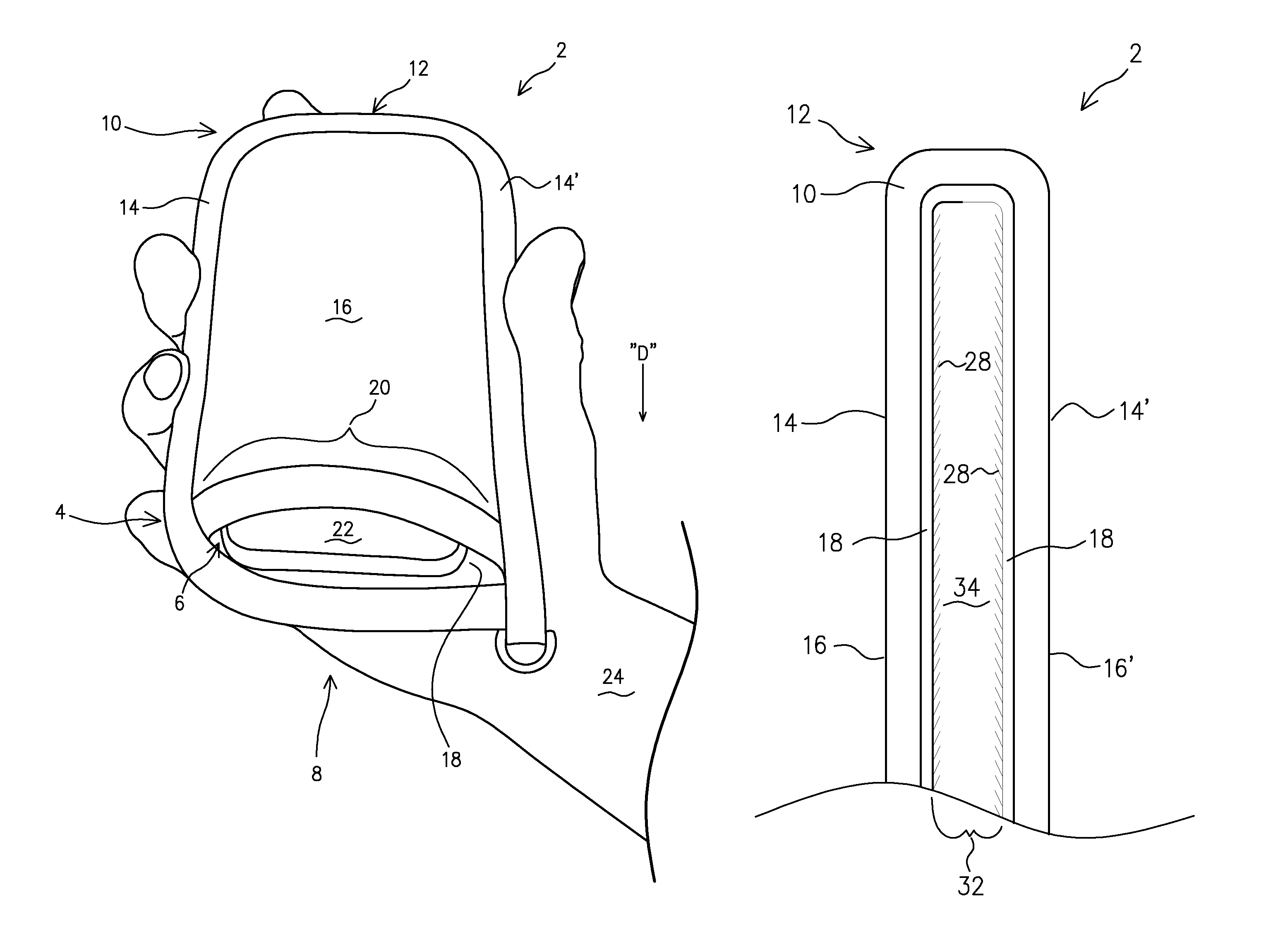
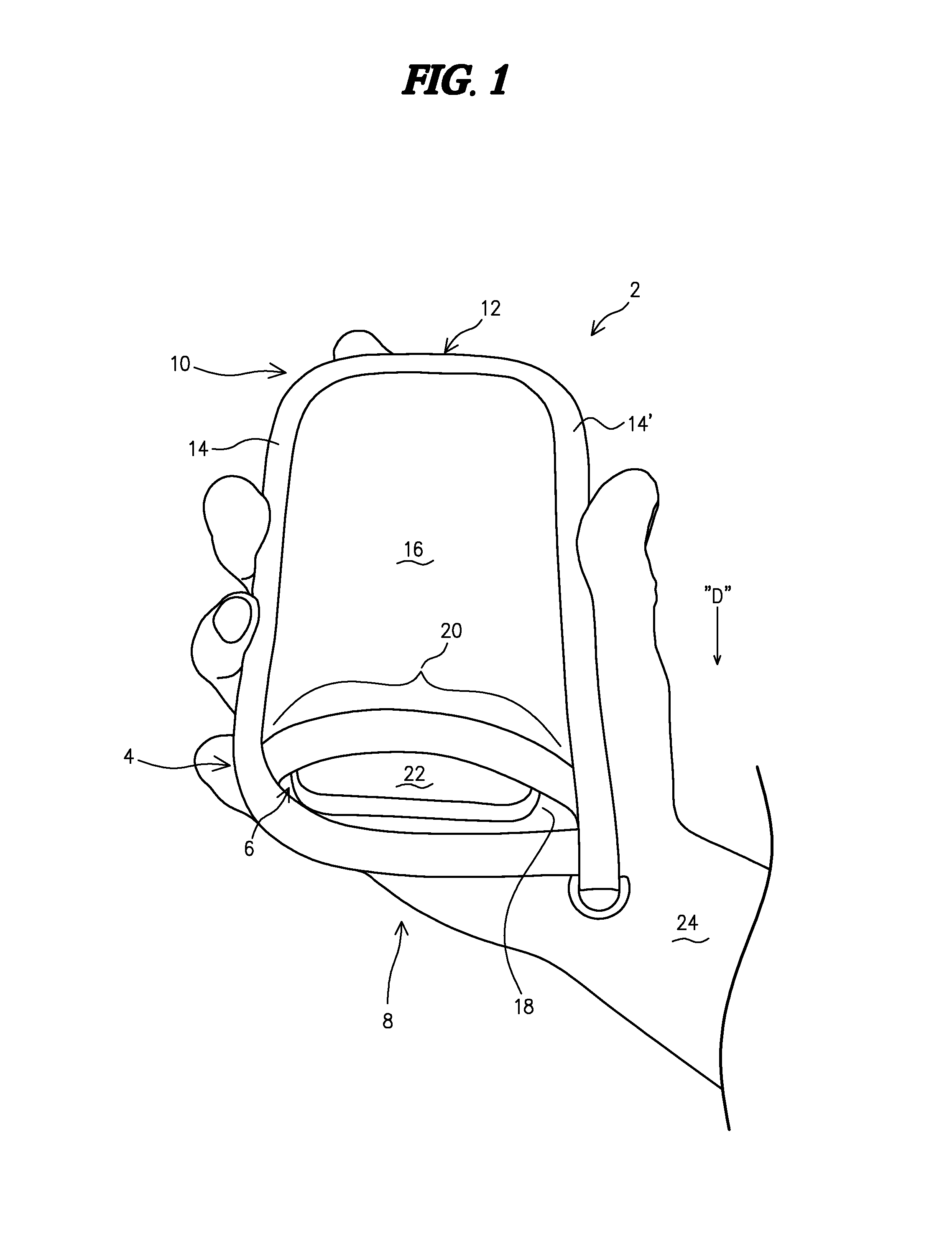
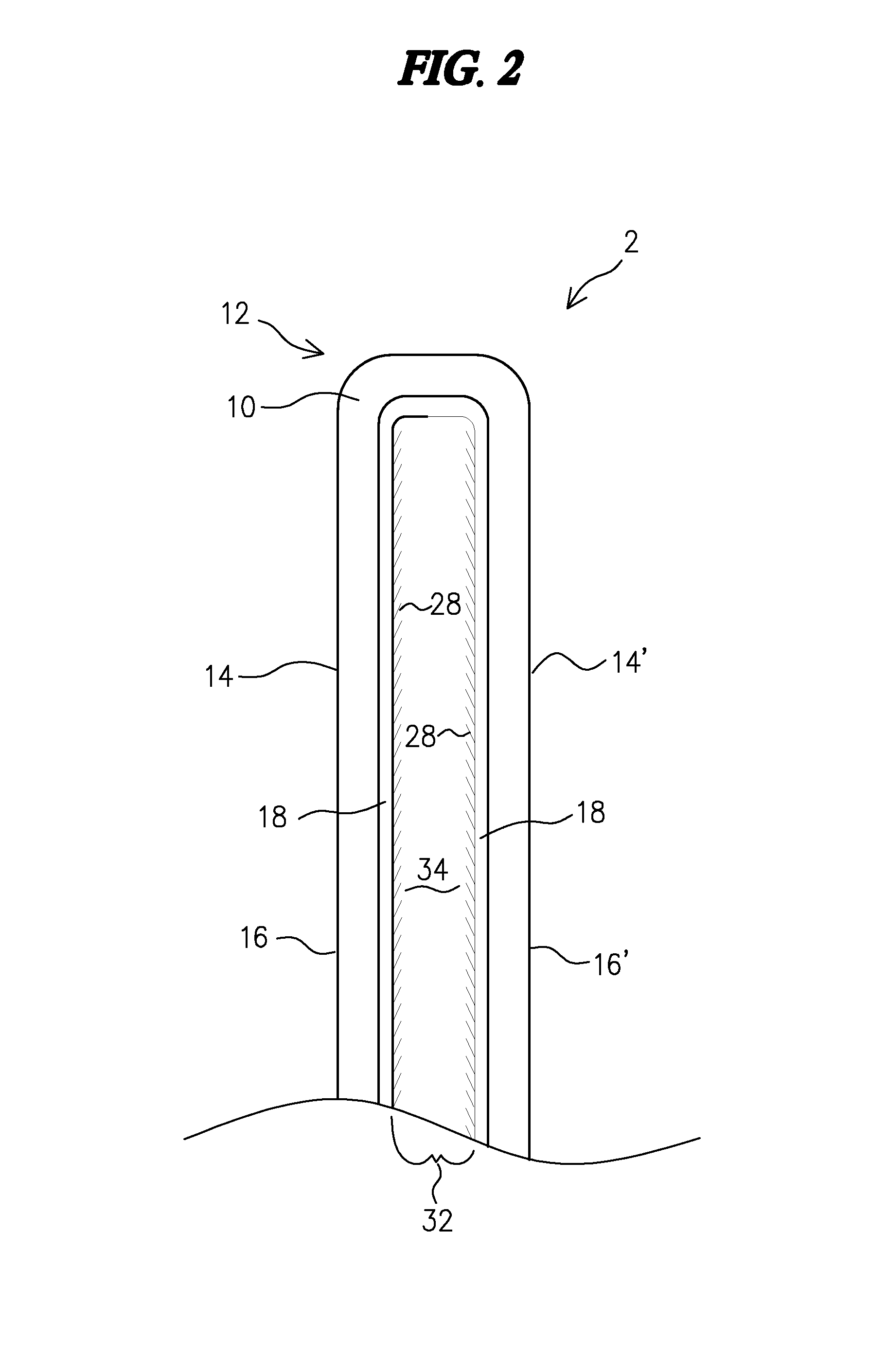
The anti-slip electronic device sleeve described in this patent is designed to protect electronic devices with smooth external contoured faces and edges. The sleeve is made of one or more fabrics and has a top margin, a closed base margin, and side walls that define an internal pocket for slidable insertion and removal of the device. The second internal layer of material has a stiff, directional nap that engages the smooth contoured faces and edges of the device when held in a downward direction. The technical effect of this invention is to provide a snug and secure fit for electronic devices in a protective environment, with enhanced grip and increased durability.

Problems solved by technology

These flaps and other fasteners take time to open and close, and impede access to the device.
Consequently, whereas sleeves have been developed to provide protection for small, hand-held electronic devices, these sleeves exhibit one or more drawbacks that make them unsuitable.
The drawbacks include: 1) fasteners over, around, or across the sleeve opening to retain the device within the sleeve; and, 2) open sleeve designs that do nothing to retain the electronic device within the sleeve when the sleeve is tipped or turned in a downward direction, thereby allowing the device to fall out of the sleeve and suffer damage.
Accordingly, there is an as of yet unmet need in the art for an electronic device protective sleeve that: 1) does not include a fastener over, around, or across the sleeve opening that impedes access to the device; and, 2) does not permit the device to fall out of the sleeve when the sleeve is tipped or turned in a generally downward direction.

Method used


Image

  • Anti-slip electronic device sleeve
  • Anti-slip electronic device sleeve
  • Anti-slip electronic device sleeve

Examples


Embodiment Construction

[0013]The following detailed description illustrates the invention by way of example, not by way of limitation of the scope, equivalents or principles of the invention. This description will clearly enable one skilled in the art to make and use the invention, and describes several embodiments, adaptations, variations, alternatives and uses of the invention.

[0014]In this regard, the invention is illustrated in the several figures, and is of sufficient complexity that the many parts, interrelationships, and sub-combinations thereof simply cannot be fully illustrated in a single patent-type drawing. For clarity and conciseness, several of the diagrams show in schematic, or omit, parts that are not essential in that diagram to a description of a particular feature, aspect or principle of the invention being disclosed. Thus, the best mode embodiment of one feature may be shown in one diagram, and the best mode of another feature will be called out in another diagram.

[0015]Anti-Slip Elect...


PUM


Abstract

A fabric-based electronic device sleeve with a stiff directional nap lining the interior of a pocket. The directional nap (or plush) of the fabric is oriented to permit easy slidable insertion of an electronic device into the sleeve's pocket, with static friction forces between the directional nap and the device preventing the device from slipping out on its own or falling from the sleeve when held in a downward direction. As a user removes the electronic device from the sleeve, a gentle pull upon pinching the device between thumb and index finger overcomes the static friction forces between the device and the directional nap lining to permit easy removal and access.

Description

FIELD OF THE INVENTION[0001]This invention relates generally to protective fabric-based covers for communication devices, and more particularly to an open sleeve having opposing internal layers of material with a stiff directional nap capable of engaging the smooth faces and contours of an electronic device to keep the device from falling out of the sleeve even when the open sleeve is held in a downward direction.BACKGROUND OF THE INVENTION[0002]Users of small electronic devices, such as cellular phones, smart phones, tablet computers, and the like, need to protect the devices when not in use. The users also need to access the devices quickly, such as when a telephone rings, or a text message is sent to the device, and the user needs to remove the device from the sleeve to answer the call or read a message.[0003]A typical sleeve design for these small electronic devices includes a fabric-based sleeve into which the device is slidably inserted. Most of these sleeve designs include a ...

Claims


Application Information

Patent Timeline
Patent Type & Authority Patents(United States)
IPC IPC(8): B65D30/08B65D30/22B65D33/00B65D33/14
CPCB65D29/02A45C11/00A45C3/001A45C2011/002A45C2011/003
Inventor BIHN, THOMAS DAMIEN
Owner TOM BIHN
Learn More