Locking Y-Valve

a technology of y-valve and lock rod, which is applied in the direction of valve details, valve arrangement, thin material handling, etc., can solve the problems of difficult to make small movements with one's fingers, unnecessary water damage, and unexpected closing

Inactive Publication Date: 2011-04-21
CRAVENER MICHAEL
View PDF3 Cites 8 Cited by
  • Summary
  • Abstract
  • Description
  • Claims
  • Application Information

AI Technical Summary

Benefits of technology

[0009]A locking Y-valve has two branches that can be independently locked open or locked closed. The liquid flow through each branch is controlled by a ball valve connected to a rotating valve column. The valve column extends through a lock plate and attaches to a housing that contains a locking mechanism. The locking mechanism has a retractable lock pin that cooperates with two recesses in the lock plate to keep the housing, valve column, and ball valve locked in place. The locking mechanism is attached to a rotatable handle outside the housing. The handle rotates under tension, retracting the lock pin from th

Problems solved by technology

This is particularly important when the free end of the hose is being carried to the fire, because the pressure of the water being discharged is so great that if discharge happens unexpectedly, a firefighter can be knocked off balance or spray huge volumes of water where it isn't needed, thereby causing water damage unnecessarily.
Unfortunately, handles on known Y-valves do not lock in place, so as the hose is being carried to the desired location for f

Method used


Image

  • Locking Y-Valve
  • Locking Y-Valve
  • Locking Y-Valve

Examples


Embodiment Construction

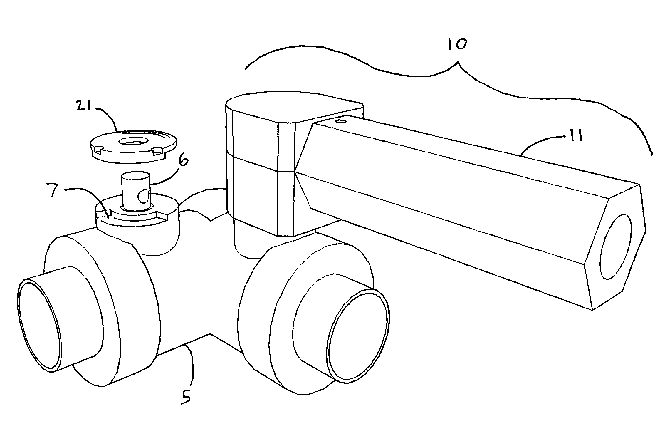
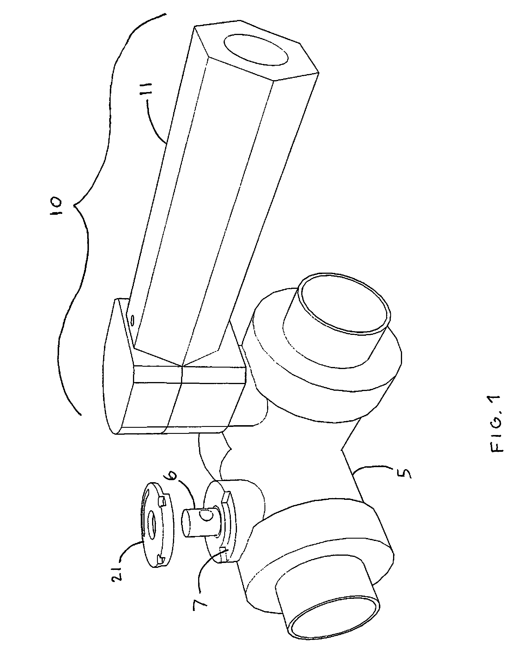
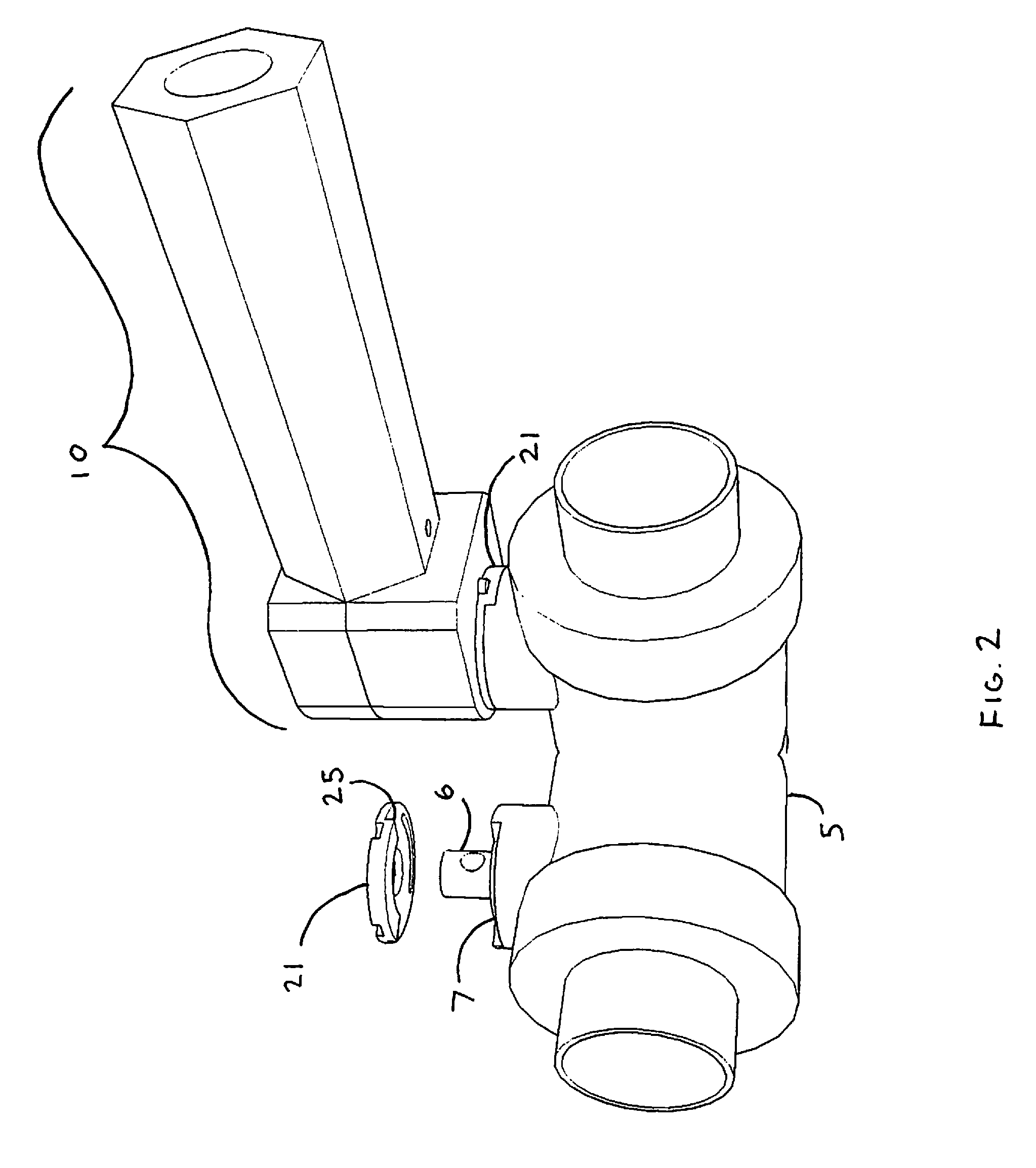
[0020]Referring to FIGS. 1 and 2, a Y-valve body 5 has two branches. The water flowing through the valve body is controlled by two ball valves (not shown), one inside each branch, as known in the art. Each ball valve is attached to a valve column 6 that rotates around its axis to open and close the ball valve. The locking handle assembly 10 of the present invention is attached to the valve column 6. The assembly 10 has a handle 11 that rotates around its own axis and around the axis of the valve column 6. When the assembly 10 is installed on the Y-valve, rotating the handle 11 about the valve column's 6 axis manipulates the ball valve. In the ball valve's closed position, the handle 11 is perpendicular to its branch of the Y; in the valve's open position, the handle is parallel to its branch of the Y as shown in FIGS. 1 and 2.

[0021]FIGS. 3-6 illustrate the components of the assembly 10. In addition to the handle 11, the assembly 10 also has a housing 12 that encases substantially al...


PUM


Abstract

A locking Y-valve has branches that can be independently locked open or locked closed. Each branch has a ball valve connected to a rotating valve column. The valve column extends through a lock plate and attaches to a housing that contains a locking mechanism. The locking mechanism has a retractable lock pin that cooperates with two recesses in the lock plate to keep the housing, valve column, and ball valve locked in place. The locking mechanism is attached to a rotatable handle outside the housing. Rotating the handle retracts the lock pin from a recess so that the handle can be moved. Releasing the handle extends the lock pin into a recess, securing the handle in place. One or more of the lock plate and housing may be integral with the Y-valve. In the preferred embodiment, the lock plate is configured to be retrofit onto existing Y-valves, so that a non-lockable Y-valve may be converted into a lockable Y-valve.

Description

CROSS-REFERENCE TO RELATED APPLICATIONS[0001]This application is a non-provisional application and claims the benefit of copending U.S. Provisional Pat. App. Ser. No. 61 / 253,427, filed Oct. 20, 2009.FIELD OF INVENTION[0002]This invention relates to fluid valves. This invention relates particularly to a mechanism for enabling the branches of a Y-valve to be locked on or off.BACKGROUND[0003]To extinguish a fire, firefighters spray water from a water source through a hose. The water sources are often fire trucks, known as pumpers, which pressurize water flowing from a fire hydrant so that the water has enough force to travel to the end of the hose and be sprayed on the fire. The hoses have couplings on each end that enable the hoses to be joined to other hoses, valves, or the water source. For example, if a hose is too short to reach a fire, hose extensions can be attached to each other with mated couplings. It is common to extend the length of a hose from a pumper by running a single ...

Claims


Application Information

Patent Timeline
IPC IPC(8): F16K31/44
CPCF16K35/10Y10T137/7256
Inventor CRAVENER, MICHAELCONNER, TOM
Owner CRAVENER MICHAEL
Why Eureka
Try Eureka