Identifying geological features in an image of an underground formation surrounding a borehole

a geological feature and image technology, applied in the field of methods to identify fractures, can solve the problems of difficult mathematical formula of non-planar fractures automatic procedures tend to fail, and fractures observed at the borehole wall are often non-planar or partial planes

Inactive Publication Date: 2011-04-21
SCHLUMBERGER TECH CORP
View PDF40 Cites 57 Cited by
  • Summary
  • Abstract
  • Description
  • Claims
  • Application Information

AI Technical Summary

Problems solved by technology

However, fractures observed at the borehole wall are often non planar or partial planes.
This non-planar nature is difficult to formulate in mathematical formula to be handled in computer programs.
Even for planar features, because fractures are often partial planes and appear in weak contrast, as opposed to bed boundaries or faults, the automatic procedures tend to fail.
This is time consuming, non-repeatable and not always accurate.

Method used


Image

  • Identifying geological features in an image of an underground formation surrounding a borehole
  • Identifying geological features in an image of an underground formation surrounding a borehole
  • Identifying geological features in an image of an underground formation surrounding a borehole

Examples


Embodiment Construction

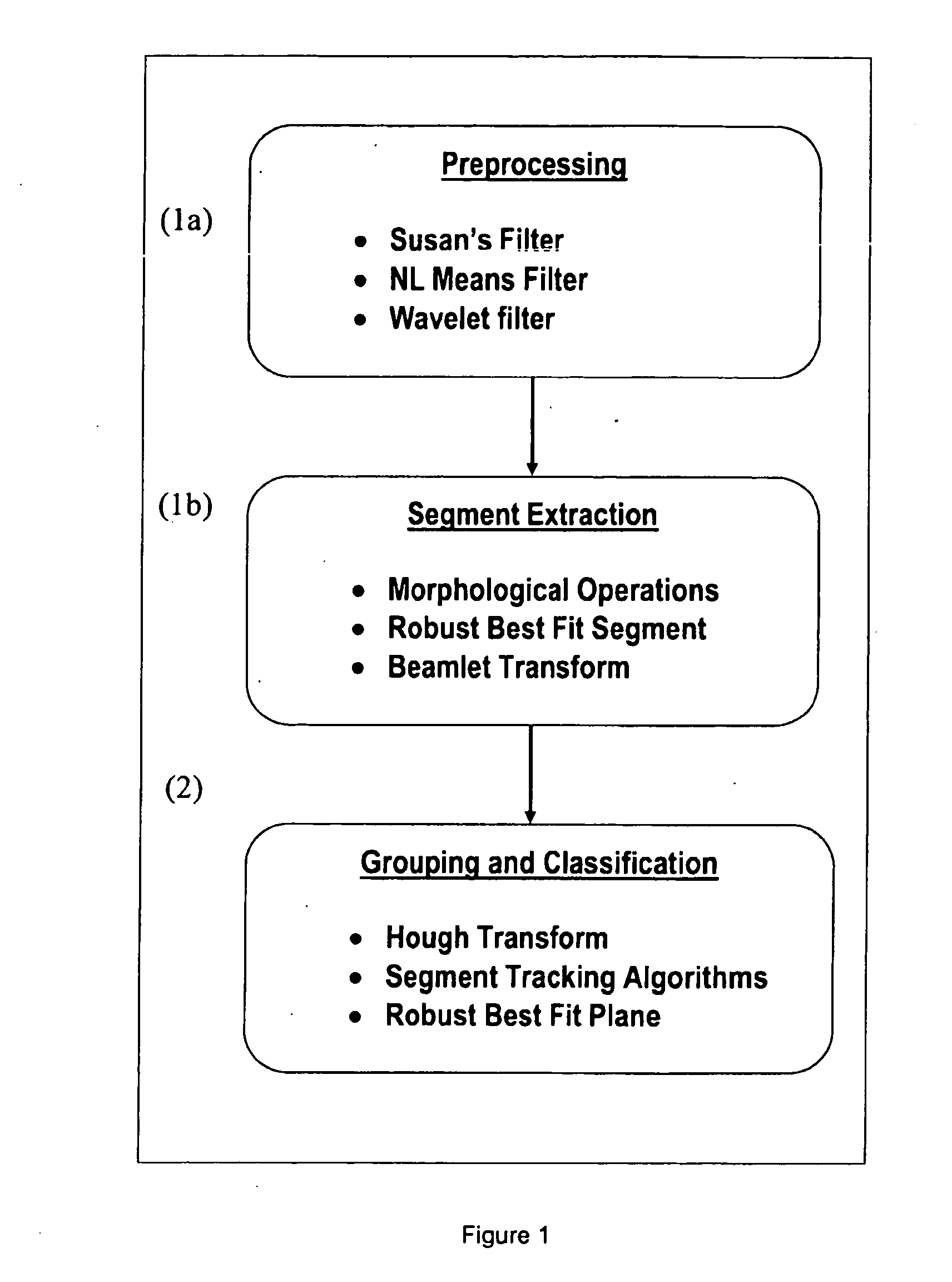
[0032]The method according to the invention is based on a search for finer features, or segments, from the borehole image, as building blocks to form the geological features. These are then grouped together, for example in user guided feature fitting methods, to classify into different geological meaningful terms. This allows characterisation of full or partial planar fractures, drilling induced fractures, other isolated non-planar fractures, as well as larger geological events like faults, bed boundaries and non-conformities.

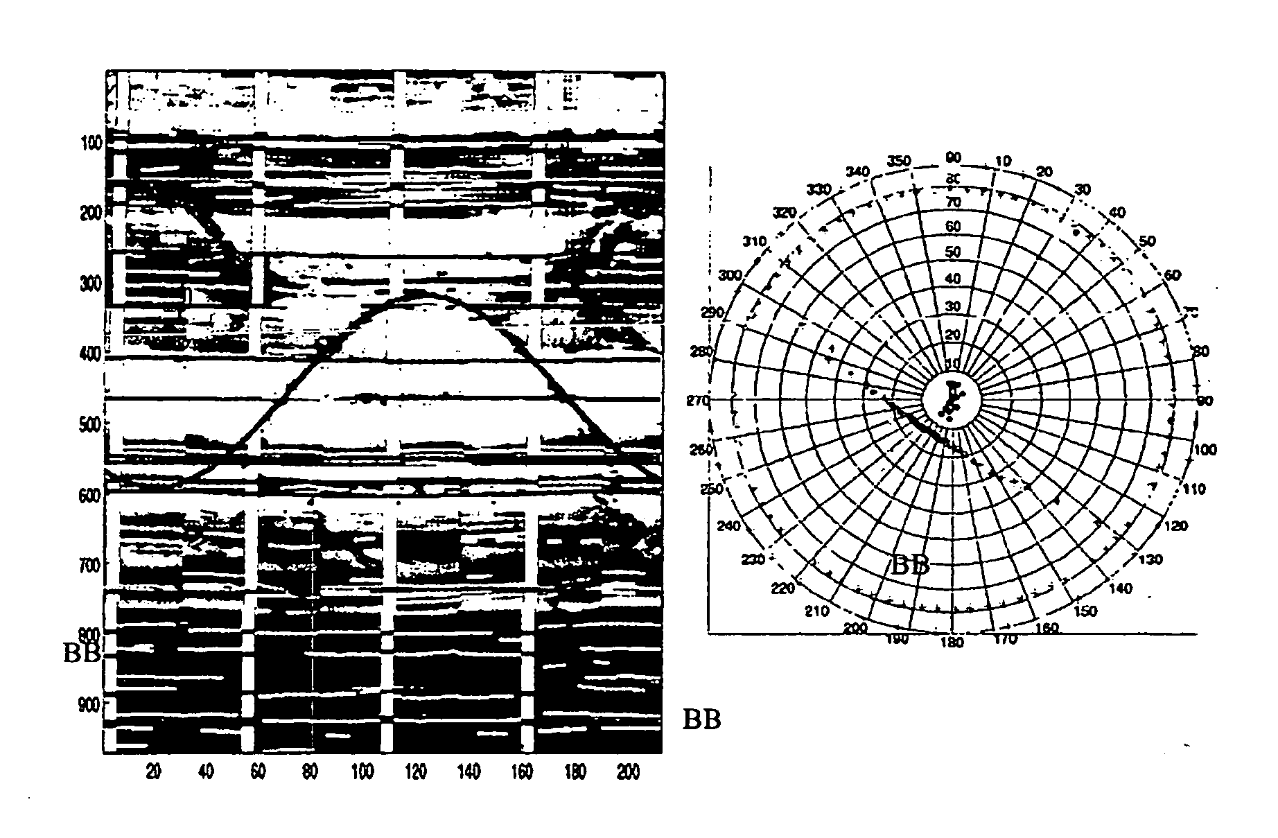
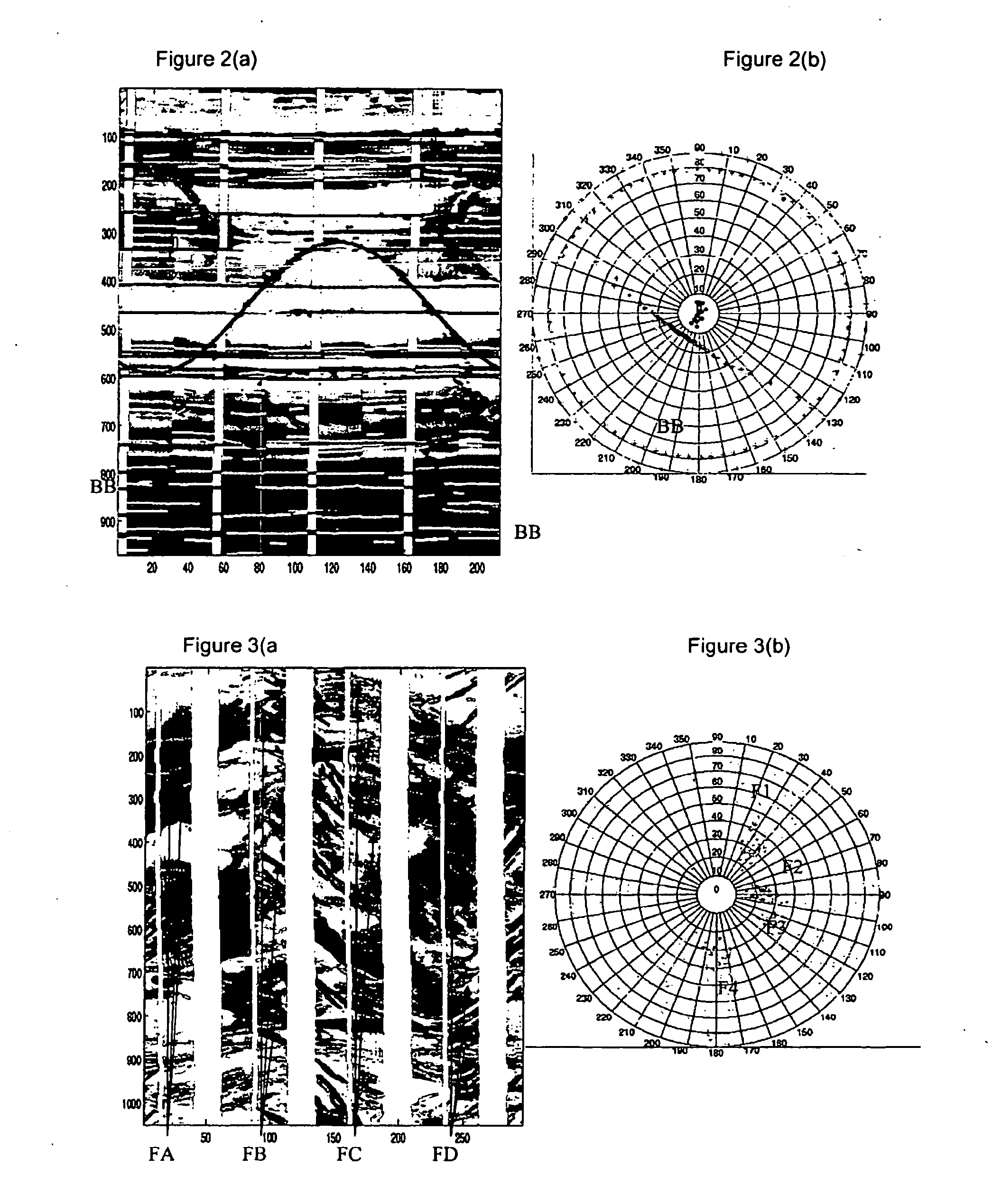
[0033]In the workflow according to a preferred embodiment of the invention, extracted segments, classified objects and groups are displayed on a stereonet plot as well as on top of 2D image display window. The grouping or classification procedure examines the different measures of conditions, such as planarity, symmetry, orientation (localisation on stereonet plot) and the discrimination of features by measurable parameters such as fracture apertures, length, c...


PUM


Abstract

A method for identifying geological features in an image of an underground formation surrounding a borehole. The method comprising: analysing the image properties to identify image regions and defining segments based on the identified image regions. Then identifying segments corresponding to a group relating to a geological feature and analysing the segments of the group to classify the feature as one of a pre-determined type.

Description

TECHNICAL FIELD[0001]This invention relates to the method to identify fractures from images such as electrical borehole images using a combination of automatic extraction of morphological features and guided classification techniques.BACKGROUND ART[0002]It is well-known in formation evaluation in the oil and gas industry to make a series of micro-measurements around the circumference of a borehole wall to try to understand the geological structure of the formations through which the borehole is drilled. One example of such a measurement technique is the EMI (Formation Micro Imager) tool of Schlumberger. This tool makes a series of overlapping micro-electrical measurements along the borehole wall, the measurement typically being reconstructed as a greyscale or colour 2D image (essentially an image of the developed, i.e. ‘unwrapped’, inside surface of the borehole wall). The electrical measurements indicate changes in the electrical properties of the formation and so can help identify...

Claims


Application Information

Patent Timeline
Patent Type & Authority Applications(United States)
IPC IPC(8): G06K9/00
CPCG01V2210/646G01V11/00
Inventor KHERROUBI, JOSSELINETCHECOPAR, ARNAUDONDA, HITOSHI
Owner SCHLUMBERGER TECH CORP
Why Eureka
Try Eureka