System and Method for Monitoring Ablation Size

a technology of ablation size and system, applied in the field of systems and methods, can solve the problems of unwanted heating of healthy tissue, large control requirements for non-invasive use of microwave energy,

Active Publication Date: 2011-04-28
TYCO HEALTHCARE GRP LP
View PDF84 Cites 38 Cited by
  • Summary
  • Abstract
  • Description
  • Claims
  • Application Information

AI Technical Summary

Benefits of technology

This patent describes a system that can monitor how big an area of tissue has been treated during an ablation process. It uses a special tool called a microwave antenna which delivers heat to the tissue to create the treatment area. There are different settings on this device that affect its performance, such as the intensity of the electricity used and the distance between the patient's skin and the surface of the tumor. By measuring these factors and adjusting them accordingly, the system can better control the formation of the treatment area and ensure it is effective while minimizing damage to surrounding healthy tissues.

Problems solved by technology

The technical problem addressed in this patent relates to finding better ways to monitor and control the area being treated during medical procedures involving the use of microwave technology. Current techniques often involve measuring the temperature of surrounding healthy tissue but these measurements come after the fact, rather than in real-time. There is also a risk of accidentally damaging healthy tissue if measures aren't taken properly.

Method used


Image

  • System and Method for Monitoring Ablation Size
  • System and Method for Monitoring Ablation Size
  • System and Method for Monitoring Ablation Size

Examples


Embodiment Construction

[0021]Embodiments of the presently disclosed system and method are described in detail with reference to the drawing figures wherein like reference numerals identify similar or identical elements. As used herein and as is traditional, the term “distal” refers to the portion which is furthest from the user and the term “proximal” refers to the portion that is closest to the user. In addition, terms such as “above”, “below”, “forward”, “rearward”, etc. refer to the orientation of the figures or the direction of components and are simply used for convenience of description.

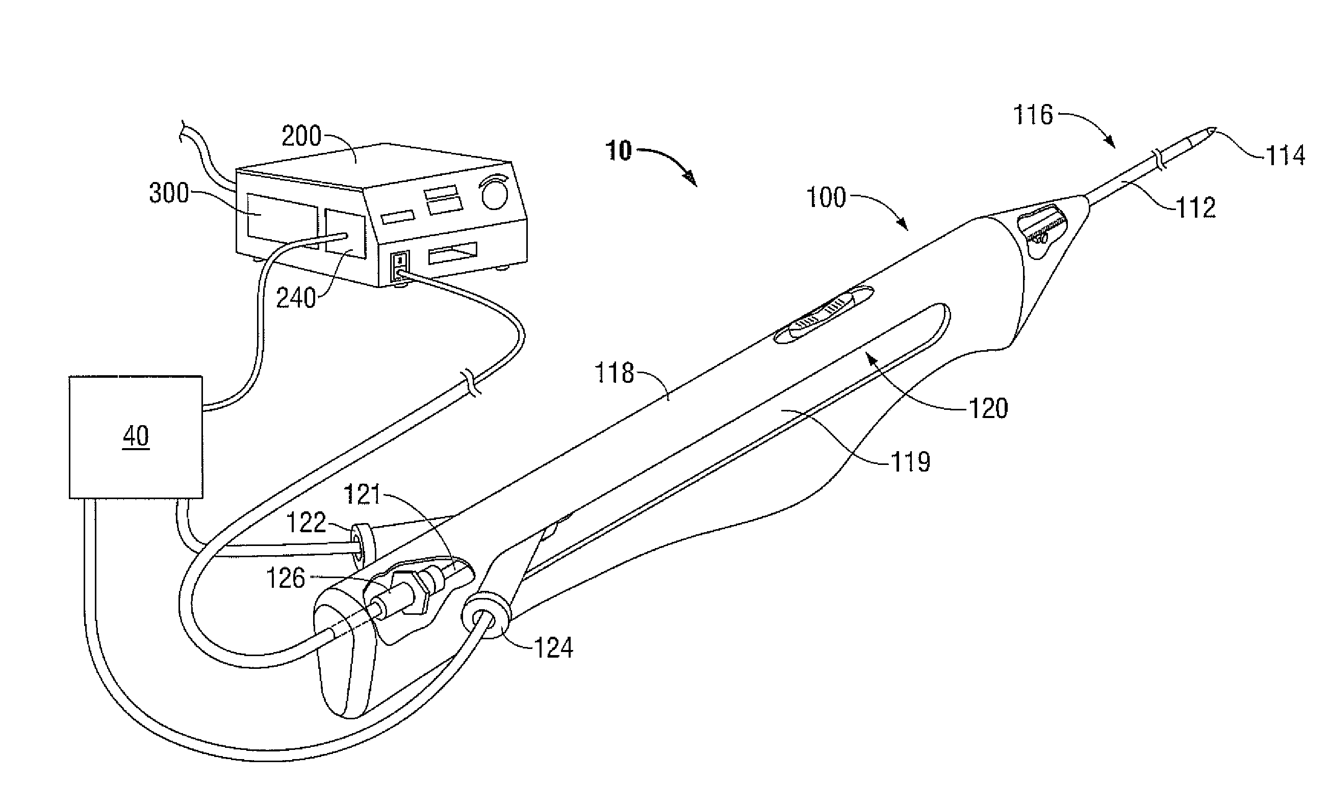
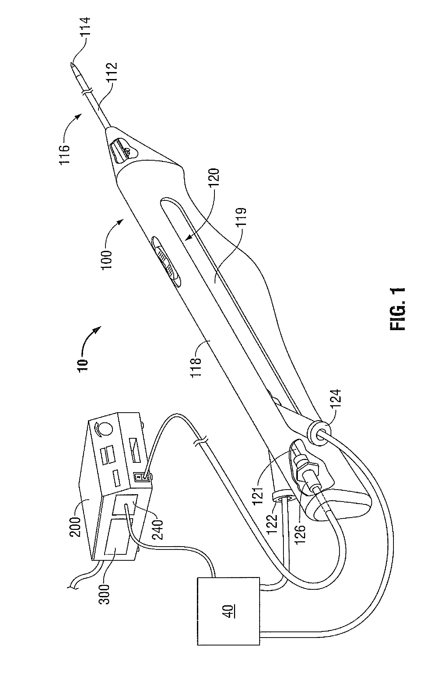
[0022]Referring now to FIG. 1, a system for monitoring ablation size is designated 10. The system 10 includes a microwave antenna 100 that is adapted to connect to an electrosurgical power source, e.g., an RF and / or microwave (MW) generator 200 that includes or is in operative communication with one or more controllers 300 and, in some instances, a fluid supply pump 40. Briefly, microwave antenna 100 includes an intr...


PUM


Abstract

A system for monitoring ablation size is provided and includes a power source including a microprocessor for executing at least one control algorithm. A microwave antenna is configured to deliver microwave energy from the power source to tissue to form an ablation zone. An ablation zone control module is in operative communication with a memory associated with the power source. The memory includes one or more data look-up tables including data pertaining to a control curve varying over time and being representative of one or more electrical parameters associated with the microwave antenna. Points along the control curve correspond to a value of the electrical parameters and the ablation zone control module triggers a signal when a predetermined threshold value of the electrical parameter(s) is measured corresponding to the radius of the ablation zone.

Description


Claims


Application Information

Patent Timeline
Owner TYCO HEALTHCARE GRP LP
Why Eureka
Try Eureka