Rotary shaft structure

Inactive Publication Date: 2011-05-05
WUN MING SYONG +1
View PDF12 Cites 0 Cited by
  • Summary
  • Abstract
  • Description
  • Claims
  • Application Information

AI Technical Summary

Benefits of technology

[0005]A primary object of the present invention is to provide a simplified but improved rotary shaft structure for coupling to and between two members, such as a display and a main body of a notebook computer, so that the display can be easily opened relative to the main body without bringing a rearward tilted main body and be slowly closed without impacting against the main body.
[0007]The first shaft can be coupled with a main body of a notebook computer, and the second shaft can be coupled with a display of the notebook computer. Through cooperative movements among the case, the first and second shafts, and the push unit, the display can be easily opened without bringing the main body to tilt rearward and be slowly closed without impacting against the main body.

Problems solved by technology

The large number of washers brings complexity in the structural design of the rotary shaft structure and inconvenience in installing the rotary shaft.
At this point, due to the weight thereof, the main body would suddenly drop from the tilted position to undesirably impact on the desktop.
This is of course very inconvenient for the user to do so.

Method used


Image

  • Rotary shaft structure
  • Rotary shaft structure
  • Rotary shaft structure

Examples


first embodiment

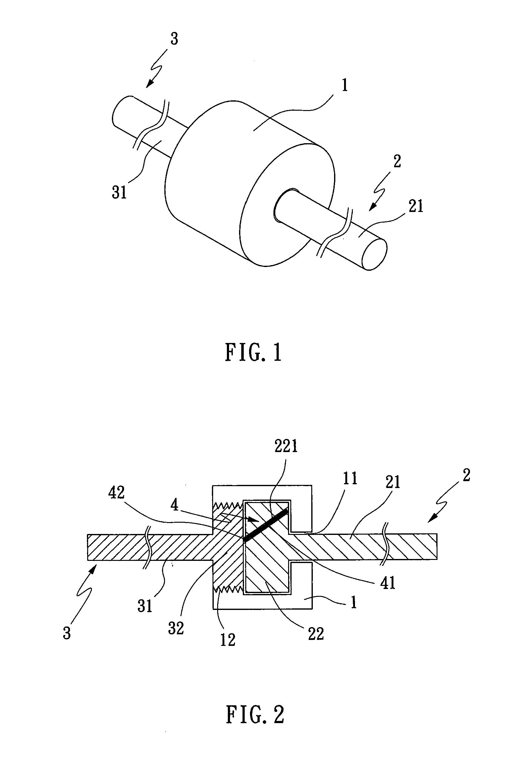
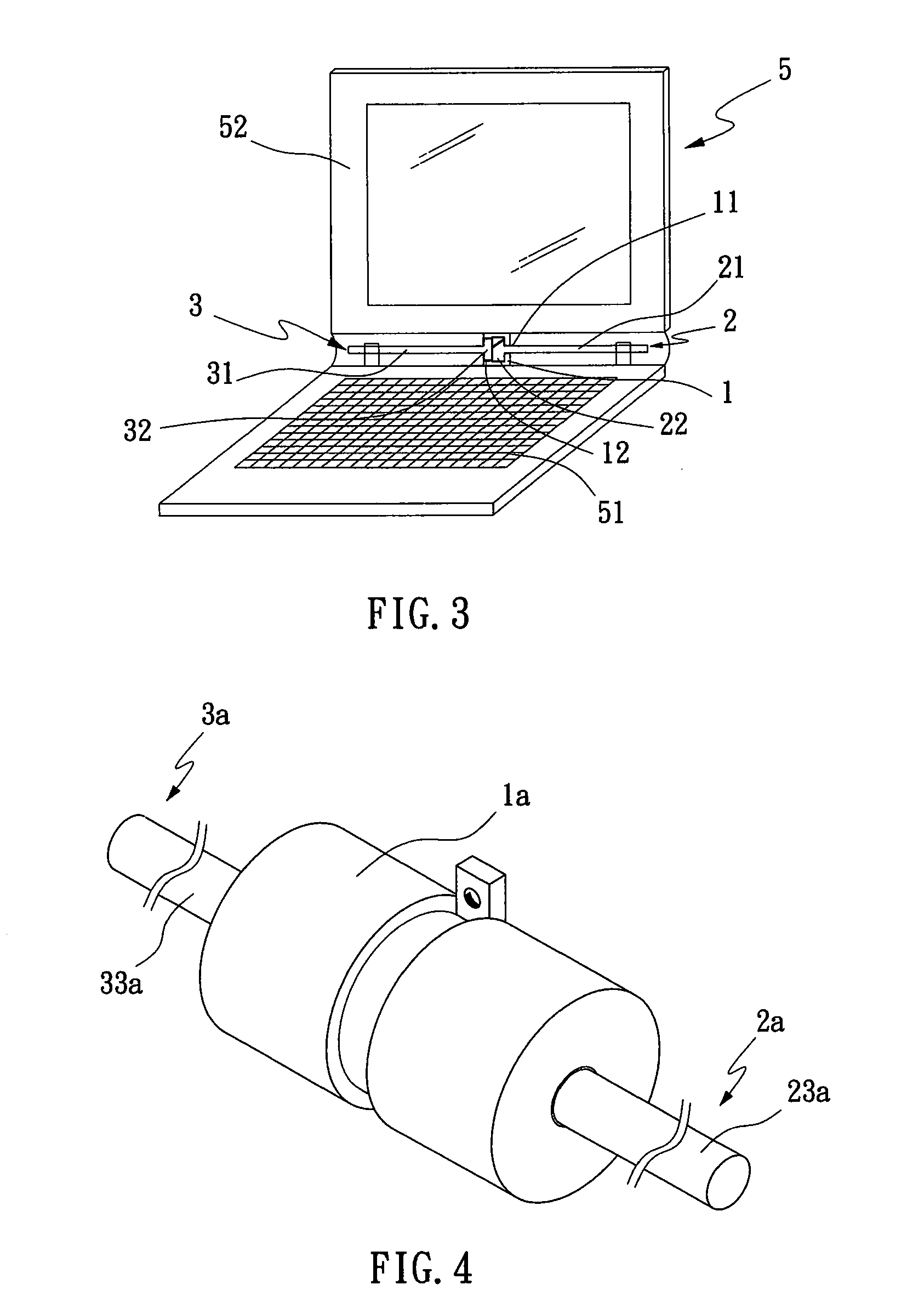
[0020]To use the rotary shaft structure according to the present invention, the shaft portion 21 of the first shaft 2 is coupled with a main body 51 of a notebook computer 5, and the shaft portion 31 of the second shaft 3 is coupled with a display 52 of the notebook computer 5. To open the display 52 of the notebook computer 5, the display 52 is lifted in a direction away from the main body 51. At this point, the second shaft 3 is brought to rotate along with the case 1 and causes the interfering element 42 of the push unit 4 to compress the elastic element 41. As a result, the interfering element 42 retracts into the receiving space 221 to allow easy open of the display 52 without tilting the main body 51 of the notebook computer 5 due to an exceeded torsional force.

[0021]And, to close the display 52 of the notebook computer 5, the display 52 is turned toward the main body 51 to cover onto the main body 51. When the display 52 is turned, the second shaft 3 is brought to rotate alon...

second embodiment

[0023]To use the rotary shaft structure according to the present invention, the shaft portions 23a, 33a of the first shaft 2a and the second shaft 3a are coupled with a main body 51 of a notebook computer 5, and the holding base 43a of the push unit 4a is coupled with a display 52 of the notebook computer 5 via the fastening plate 47a. To open the display 52 of the notebook computer 5, the display 52 is lifted in a direction away from the main body 51. At this point, the case 1a and the holding base 43a of the push unit 4a are brought to rotate at the same time. Meanwhile, since the interfering elements 42 are not in frictional contact with the first and the second shaft 2a, 3a, allowing the display 52 to be easily opened without tilting the main body 51 of the notebook computer 5 due to an exceeded torsional force.

[0024]And, to close the display 52 of the notebook computer 5, the display 52 is turned toward the main body 51 to cover onto the main body 51. When the display 52 is tur...


PUM


Abstract

A rotary shaft structure includes a case, a first shaft fitted in the case with an end of the first shaft outward extended from an end of the case; a second shaft fitted in the case with an end of the second shaft outward extended from an opposing end of the case opposite to the first shaft; and a push unit arranged in the case to locate between the first and the second shaft. The rotary shaft structure is simplified and can be coupled to and between a main body and a display of a notebook computer, enabling easy open of the display without causing a rearward tilted main body and slow close of the display without impacting against the main body.

Description

FIELD OF THE INVENTION[0001]The present invention relates to an improved rotary shaft structure, and more particularly to a simplified rotary shaft structure for coupling to and between two members to enable easy open of one member relative to the other member and slow close of one member without impacting against the other member.BACKGROUND OF THE INVENTION[0002]A conventional rotary shaft structure for a notebook computer includes a first fixing plate and a second fixing plate respectively connected to a main body and a display of the notebook computer. A shaft is extended from one side of the first fixing plate, and a washer is riveted to an end of the shaft. A plurality of washers is provided on the shaft at two sides of the second fixing plate, so that the washers are in frictional contact with the second fixing plate to thereby provide an appropriate torsion, allowing the first and the second fixing plate to rotate properly.[0003]In the above-described conventional rotary shaf...

Claims


Application Information

Patent Timeline
IPC IPC(8): E05D11/08
CPCE05F5/02E05Y2201/21E05Y2201/234E05Y2201/26Y10T16/5403E05Y2900/606G06F1/162G06F1/1681E05Y2201/266E05Y2999/00
Inventor WUN, MING-SYONGCHAN, CHUN-CHANG
Owner WUN MING SYONG
Why Eureka
Try Eureka