Lower-back supporting structure for a bed or a chair

a supporting structure and bed frame technology, applied in the direction of beds, chairs, sofas, etc., can solve the problems of insomnia, lack of sufficient rest, and prior art bed frames all lack a lower-back support function, so as to improve the comfort of the bed frame or chair, ease the pain of the lower back, and increase the lift height of the supporting member

Inactive Publication Date: 2011-05-05
RUOEY LUNG ENTERPRISE
View PDF5 Cites 11 Cited by
  • Summary
  • Abstract
  • Description
  • Claims
  • Application Information

AI Technical Summary

Benefits of technology

When the extendable rod of the driver is extended, the extendable rod pushes the sliding rod towards the outer arcuate regions of the slide slots, and the first front cotter holes of the scissor lifts are pushed in the same direction so the scissor lifts rotate around their pivots. A maximum distance between the first front cotter hole and the rear cotter hole is then reached. Alternatively, when the extendable rod of the driver contracts, the through hole of the extendable rod pulls the sliding rod to slide towards the inner arcuate regions of the slide slots, and with the sliding rod being pivoted to the first front cotter holes of the scissor lifts the sliding rod simultaneously pulls the first front cotter holes to slide towards the rear cotter holes. Meanwhile, the scissor lifts rotate around their pivots, and a minimum distance between the first front cotter holes and the rear cotter holes is then reached. Additionally, the second front cotter holes and the rear rotating pins of the scissor lifts also move to closer to each other. The rear rotating pins are pivoted on the rotating holes of the supporting member, and the rear rotating pins of the scissor lifts lift the ends having the rotating holes of the supporting member. The second front cotter holes with the sliding pin slides and pushes against the slide track of the supporting member. Therefore, with the contraction of the driver and the simultaneous rotation of the scissor lifts, the supporting member is able to lift up while remaining horizontal.
The lower-back supporting structure utilizes the driver to push the sliding rod along the slide slots, and with the scissoring movement of the scissor lifts the supporting is lifted horizontally. This simple assembly structure can provide lower-back support to improve the comfort of the bed frame or chair. Moreover, the scissor lifts both are an X-shaped frame and capable of scissoring movement around the pivots to increase the lift height of the supporting member. Therefore, the lower-back supporting structure can help users to ease their lower-back pain.

Problems solved by technology

However, due to the stresses of modern life, many people suffer from insomnia and therefore suffer from a lack of sufficient rest.
However, these prior art bed frames all lack a lower-back support function.
If, when the user is laying flat, his or her lower-back is not supported by the bed surface, the user cannot experience the most comfortable posture or release the stresses around the lower-back.
However, the prior art lower-back support structure requires manual operation which is inconvenient, and the elastic sheet cannot provide sufficient support height.

Method used


Image

  • Lower-back supporting structure for a bed or a chair
  • Lower-back supporting structure for a bed or a chair
  • Lower-back supporting structure for a bed or a chair

Examples


Embodiment Construction

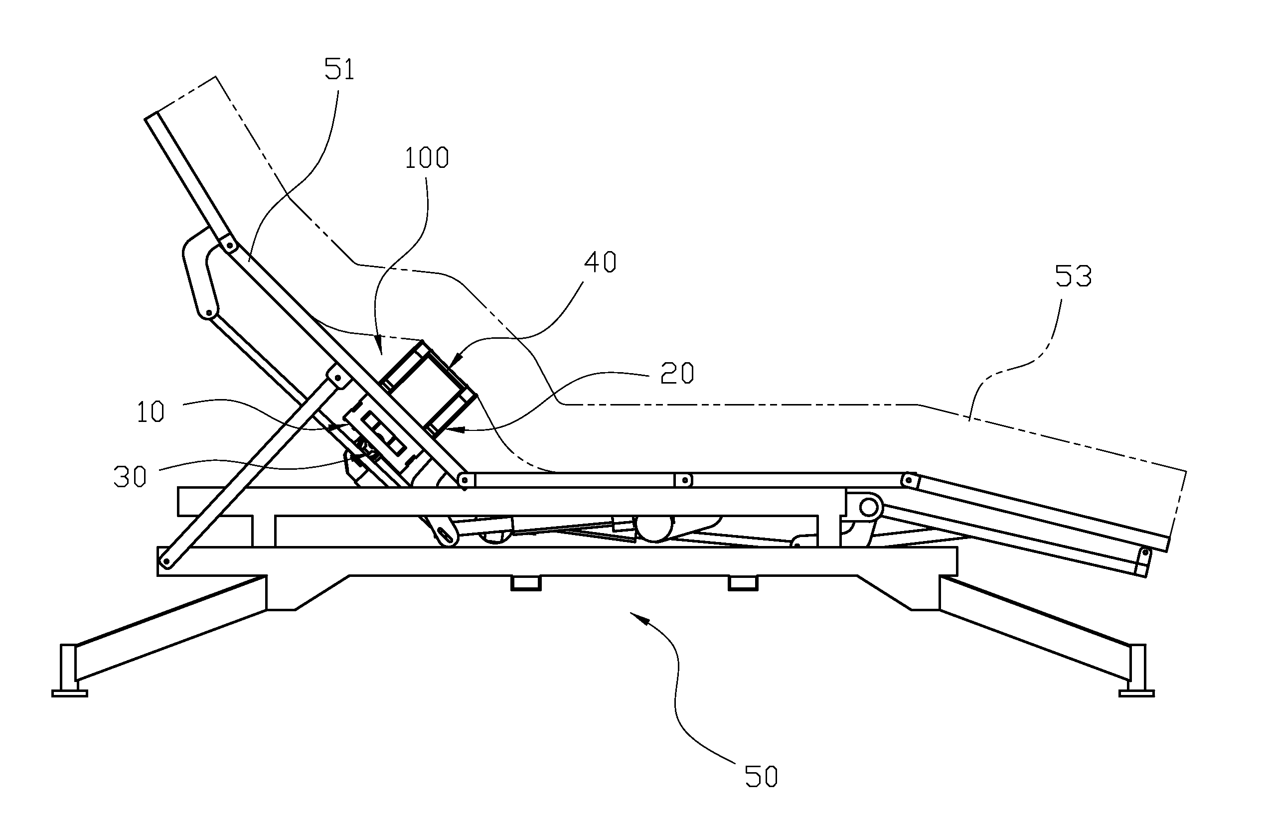
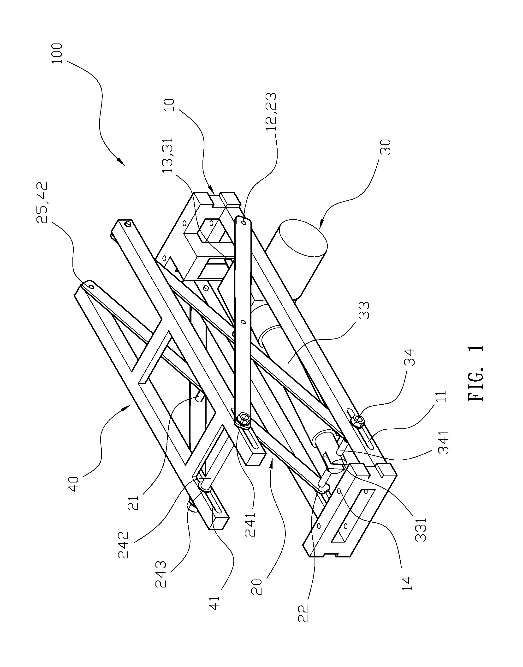
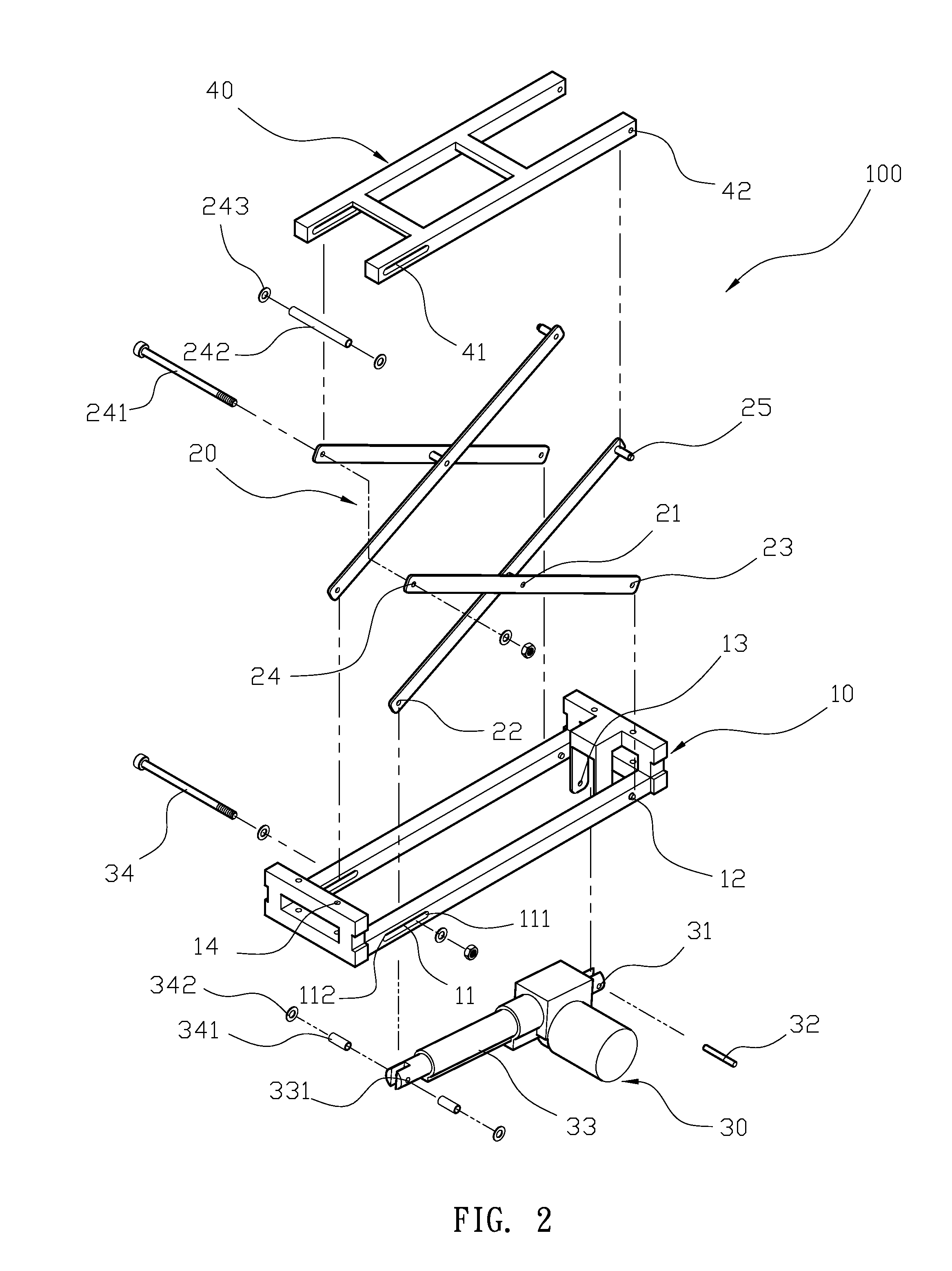
Please refer to FIG. 1 and FIG. 2. An embodiment lower-back supporting structure 100 for a bed or a chair comprises a sliding base 10, two scissor lifts 20, a driver 30 and a supporting member 40. The sliding base 10 is a rectangular frame, and front ends and rear ends of two length-wise sides respectively have a pair of slide slots 11 and a pair of rotating pins 12. Each slide slot 11 is an elongate slot having an inner arcuate region 111 and an outer arcuate region 112 at two respective ends. A securing portion 13 is disposed on a down-extended portion between the two rotating pins 12, and the sliding base 10 includes a plurality of locking apertures 14. The two scissor lifts 20 both are an X-shaped frame having a pivot 21; two bottom ends of each has a first front cotter hole 22 and a rear cotter hole 23, and two top ends of each has a second front cotter hole 24 and rear rotating pin 25. The first front cotter hole 22 of each scissor lift 20 is aligned with the slide slot 11 of ...


PUM


Abstract

A lower-back supporting structure for a bed or a chair includes a sliding base, two scissor lifts, a driver and a supporting member. The sliding base has a pair of slide slots and a pair of rotating pins, a securing portion between the two rotating pins, and a plurality of the locking apertures. Two scissor lifts both have an X-shaped frame having a pivot. A driver has a positioning end, an extendable rod, a through hole and a sliding rod placed through the slide slot, the through hole and the first front cotter holes. A supporting member has a pair of slide tracks and a pair of rotating holes. The driver drives the sliding rod along the slide slot of the sliding base to shorten the extendable rod, the scissor lifts rotate around the pivots to lift such that the supporting member is pushed away from the sliding base.

Description

BACKGROUND OF THE INVENTION1. Field of the InventionThe present invention relates to a lower-back supporting structure for a bed or a chair, and more particularly to a lower-back supporting assembly that provides lower-back support to improve the comfort afforded by a bed frame or chair, which employs scissor lifts that are capable of a scissoring movement to increase the lift height of the supporting member, thereby providing a lower-back supporting structure that can help users suffering from lower-back pain.2. Description of the Related ArtCurrently, most bed frames are designed for a user to lay flat while sleeping, and a typical bed frame includes four legs and supports. However, due to the stresses of modern life, many people suffer from insomnia and therefore suffer from a lack of sufficient rest. Consequently, many bed frames have included additional features, such as providing head or leg lifting capabilities, and the user can select and adjust a suitable position for him o...

Claims


Application Information

Patent Timeline
Patent Type & Authority Applications(United States)
IPC IPC(8): A47C7/46A47C3/00A47C16/00A47C21/00A47C31/00
CPCA47C20/027A47C7/425
Inventor SHIH, LUNG-TAN
Owner RUOEY LUNG ENTERPRISE
Why Eureka
Try Eureka