Programmable security system with transmitter

a security system and transmitter technology, applied in the direction of program control, testing/monitoring control system, instruments, etc., can solve the problems of expensive demolition and installation, inconvenient installation, and inconvenient installation and maintenan

Inactive Publication Date: 2011-05-05
SHAFFER THOMAS G
View PDF13 Cites 70 Cited by
  • Summary
  • Abstract
  • Description
  • Claims
  • Application Information

AI Technical Summary

Problems solved by technology

This process requires extensive demolition and repair to existing walls.
This demolition and installation is expensive and running the wires on the outside of the walls to reduce cost is not aesthetically acceptable.
This process can be expensive and limits an owner's ability to change security monitoring companies because a professional installer is required to install the system.
In each case this is a costly replacement that requires a professional service technician to make the replacement.

Method used


Image

  • Programmable security system with transmitter
  • Programmable security system with transmitter
  • Programmable security system with transmitter

Examples


Embodiment Construction

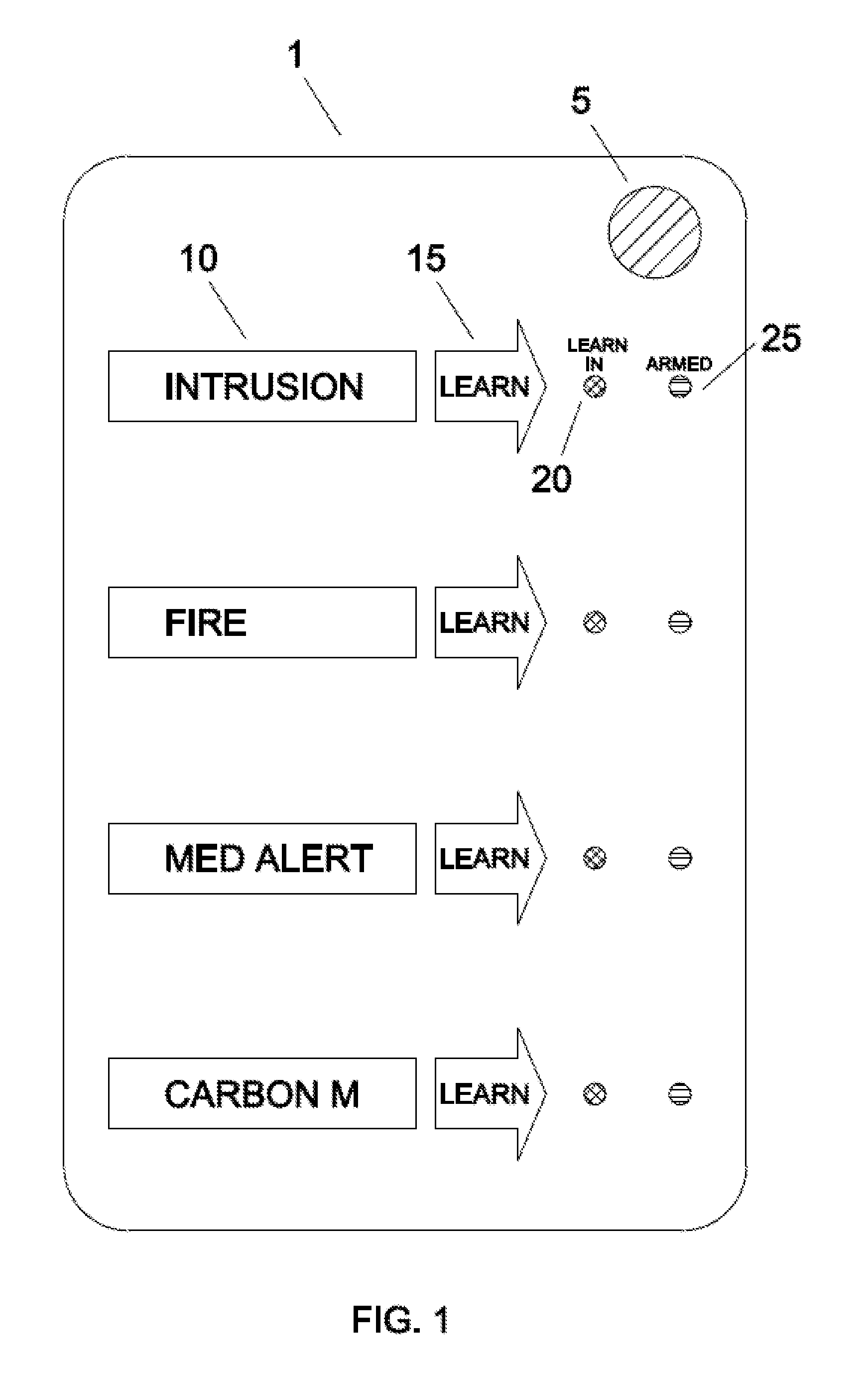
[0016]FIG. 1 depicts a panel 1 of a security system program box. Microphone slot 5 allows sound to pass through the panel 1. Label 10 indicates the type of alarm to be recognized. Learn button 15 is used to start the recording process for a particular alarm. Learn light 20 indicates when an alarm is being learned, label 10 indicates when an alarm has been learned, and armed light 25 indicates when the corresponding alarm is armed.

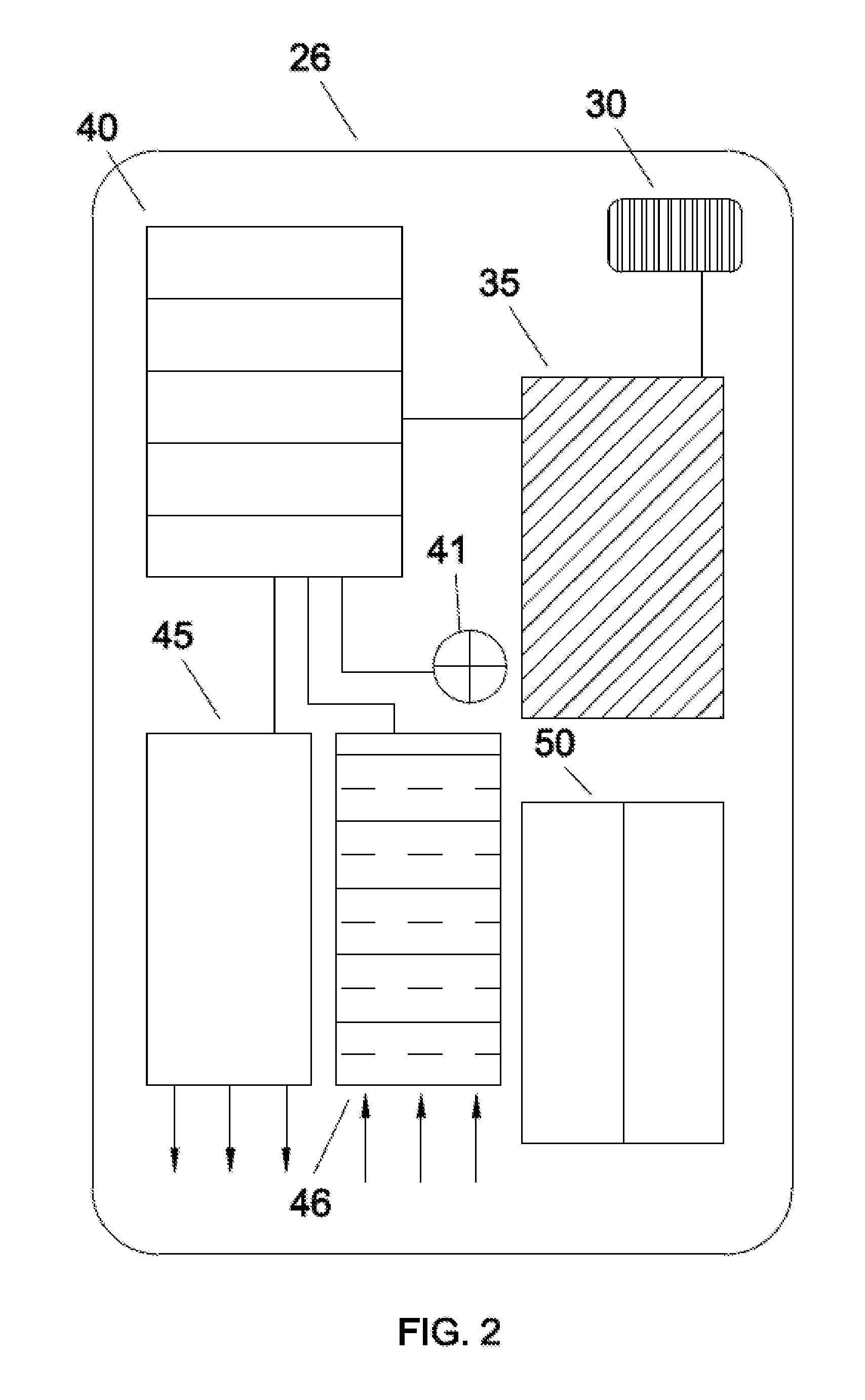
[0017]In one embodiment the panel is used by pressing the learn button 15 and learn light 20 turns on. The user the goes to an audible alarm and waits for fifteen seconds for a beep. After the beep, the user activates the audible alarm. The sound from the audible alarm passes through the microphone slot 5 to microphone 30 (FIG. 2). Once the alarm sound has been recorded and recognized the learn light 15 turns off. Armed light 25 is on while the alarm is armed. The audible alarm to be programmed in can be activated by pressing the test button or by tripping ...


PUM


Abstract

A security system comprising an audible alarm with a microphone within acoustic range of the audible alarm. A storage circuit configured to store at least one acoustic fingerprint. A processing circuit coupled to the storage circuit and configured to create a first acoustic fingerprint from a first signal from the microphone and save the first acoustic fingerprint on the storage circuit. The processing circuit further configured to create a second acoustic fingerprint from a second signal from the microphone and compare the first acoustic fingerprint to the second acoustic fingerprint. The processing circuit further configured to transmit a set of data if the first acoustic fingerprint matches the second acoustic fingerprint. A transmitter coupled to the processing circuit and configured to transmit the set of data. The security system has the advantage to be installed without using wire connections to existing alarm systems or decode their radio frequencies.

Description

BACKGROUND OF THE INVENTION[0001]In current security systems a central processing unit receives a signal from a detection device such as a smoke detector, motion sensor, carbon monoxide sensor etc. These signals are carried from the detection devices to the central processing unit through a wiring system. For this reason, installing a new security system in an existing home requires running wiring from the detection devices to the central process unit. This process requires extensive demolition and repair to existing walls. This demolition and installation is expensive and running the wires on the outside of the walls to reduce cost is not aesthetically acceptable.[0002]Many of the existing security systems are installed as part of monitoring agreement where a security company sells the central processing unit and provides monitoring services for a monthly fee. Changing to a different monitoring company requires changing the central processing unit to meet the new monitoring company...

Claims


Application Information

Patent Timeline
Patent Type & Authority Applications(United States)
IPC IPC(8): G06F7/04G08B3/00
CPCG08B1/08G08B25/14G08B25/008
Inventor SHAFFER, THOMAS
Owner SHAFFER THOMAS G
Why Eureka
Try Eureka