High density multi-view image display system and method with active sub-pixel rendering

a multi-view image and display system technology, applied in the field of high density multi-view image display system and method with active subpixel rendering, can solve the problems of viewing fatigue, reducing the resolution of the display, and reducing the quality of 3d images

Active Publication Date: 2011-05-05
SAMSUNG ELECTRONICS CO LTD
View PDF14 Cites 62 Cited by
  • Summary
  • Abstract
  • Description
  • Claims
  • Application Information

AI Technical Summary

Benefits of technology

The invention provides an image display system that can track the user's eye movements and adjust its output accordingly. It uses multiple pixels called "sub-pixels," each containing different colors based on their location within the visual field. By changing which parts of the screen are shown to the user's eyes, it creates a realistic experience for them. This technology allows for improved virtual reality experiences and better control over how images appear on screens.

Problems solved by technology

The technical problem addressed in this patent text relates to improving the quality of autostereoscopic displays by reducing viewing fatigue caused by the limitation of the viewing areas and ensuring that the viewer's perspective does not affect the perceived quality of the virtual objects. Additionally, it proposes addressing these issues through a combination of techniques such as increased use of multiple viewpoints and improved visual acuity over time.

Method used


Image

  • High density multi-view image display system and method with active sub-pixel rendering
  • High density multi-view image display system and method with active sub-pixel rendering
  • High density multi-view image display system and method with active sub-pixel rendering

Examples


Embodiment Construction

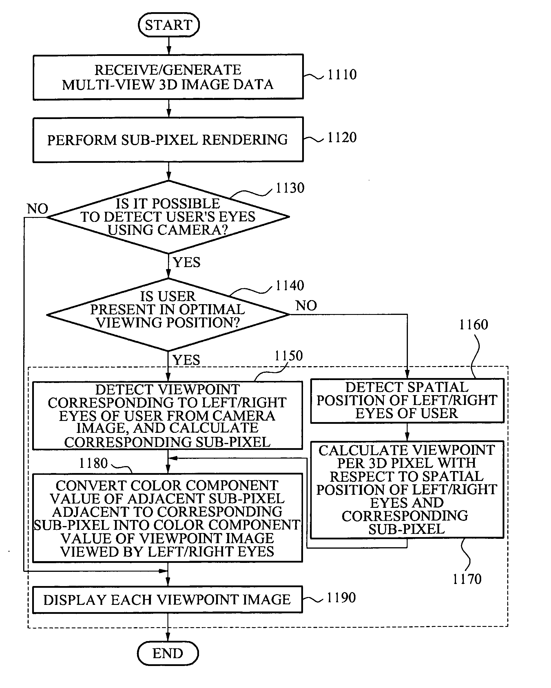
[0036]Reference will now be made in detail to one or more embodiments, illustrated in the accompanying drawings, wherein like reference numerals refer to like elements throughout. In this regard, embodiments of the present invention may be embodied in many different forms and should not be construed as being limited to embodiments set forth herein. Accordingly, embodiments are merely described below, by referring to the figures, to explain aspects of the present invention.

[0037]Embodiments may relate to an image display system and method that may track a position of left / right eyes of a user to determine viewpoint information for an image viewed by the user, and in one or more embodiments provide a three-dimensional (3D) image without or with limited crosstalk or distortion of a 3D effect, using active sub-pixel rendering based on the determined viewpoint information. By performing sub-pixel rendering instead of only pixel-rendering, the number of displayed viewpoints may be increas...


PUM


Abstract

Provided are a high density multi-view image display system and method based on active sub-pixel rendering. The image display system may perform a rendering with respect to a viewpoint image in a pixel unit, using a viewpoint varying based on a position of left/right eyes of a user.

Description


Claims


Application Information

Patent Timeline
Owner SAMSUNG ELECTRONICS CO LTD
Why Eureka
Try Eureka