

Information processing method, information processing apparatus, and image sensing apparatus
a technology of information processing and image sensing, applied in the direction of instruments, static indicating devices, optical elements, etc., can solve the problem of generating a sense of discomfort in stereoscopic vision
- Summary
- Abstract
- Description
- Claims
- Application Information
AI Technical Summary
Benefits of technology
Problems solved by technology
Method used
Image

Examples
first embodiment
[0072] In this embodiment, when the image of a virtual space formed from a virtual object including at least one part is superimposed on the image of the physical space and presented to the observer, pieces of information about the parts are also presented to the observer. A system to execute such presentation will be described below.
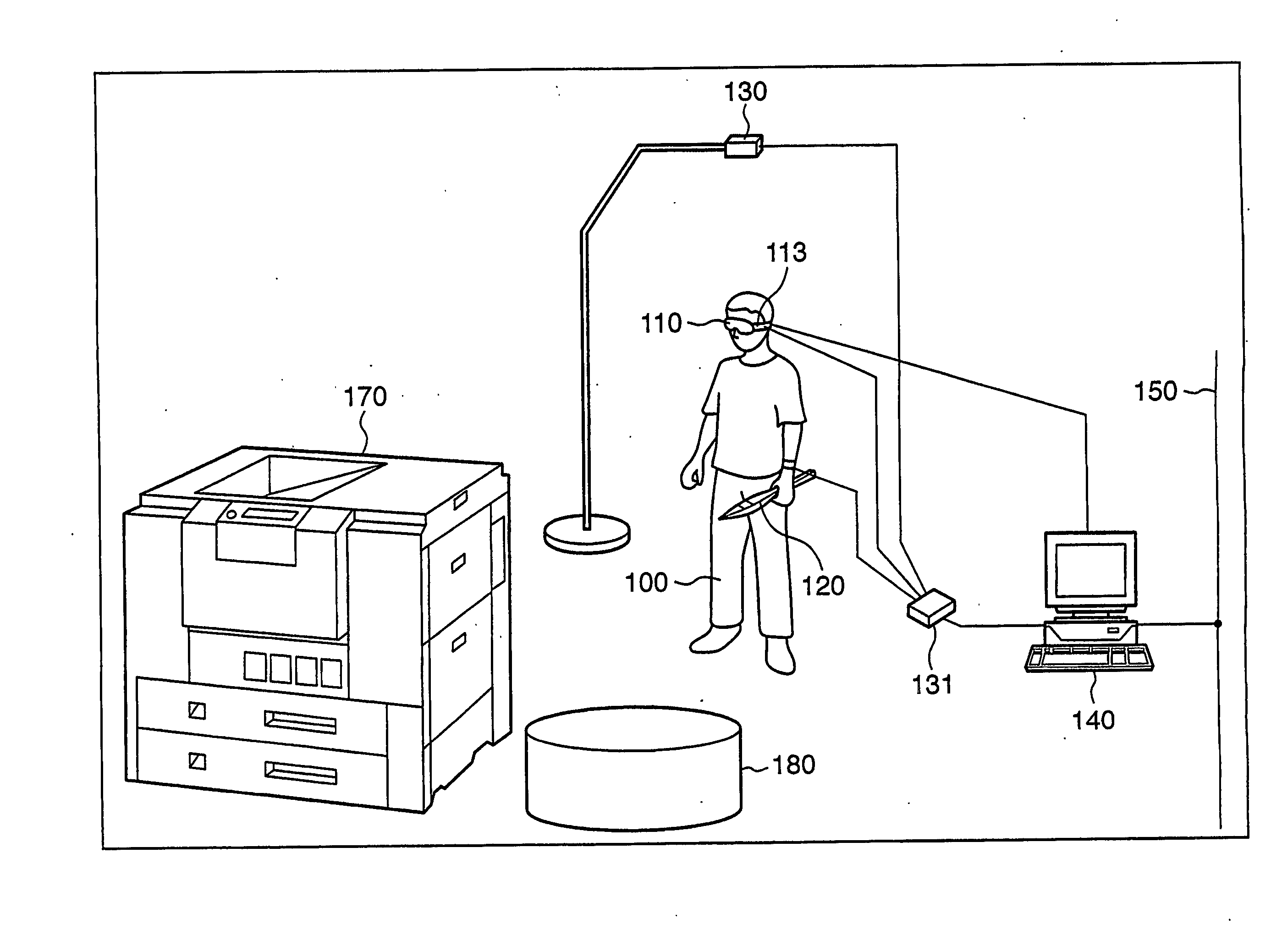
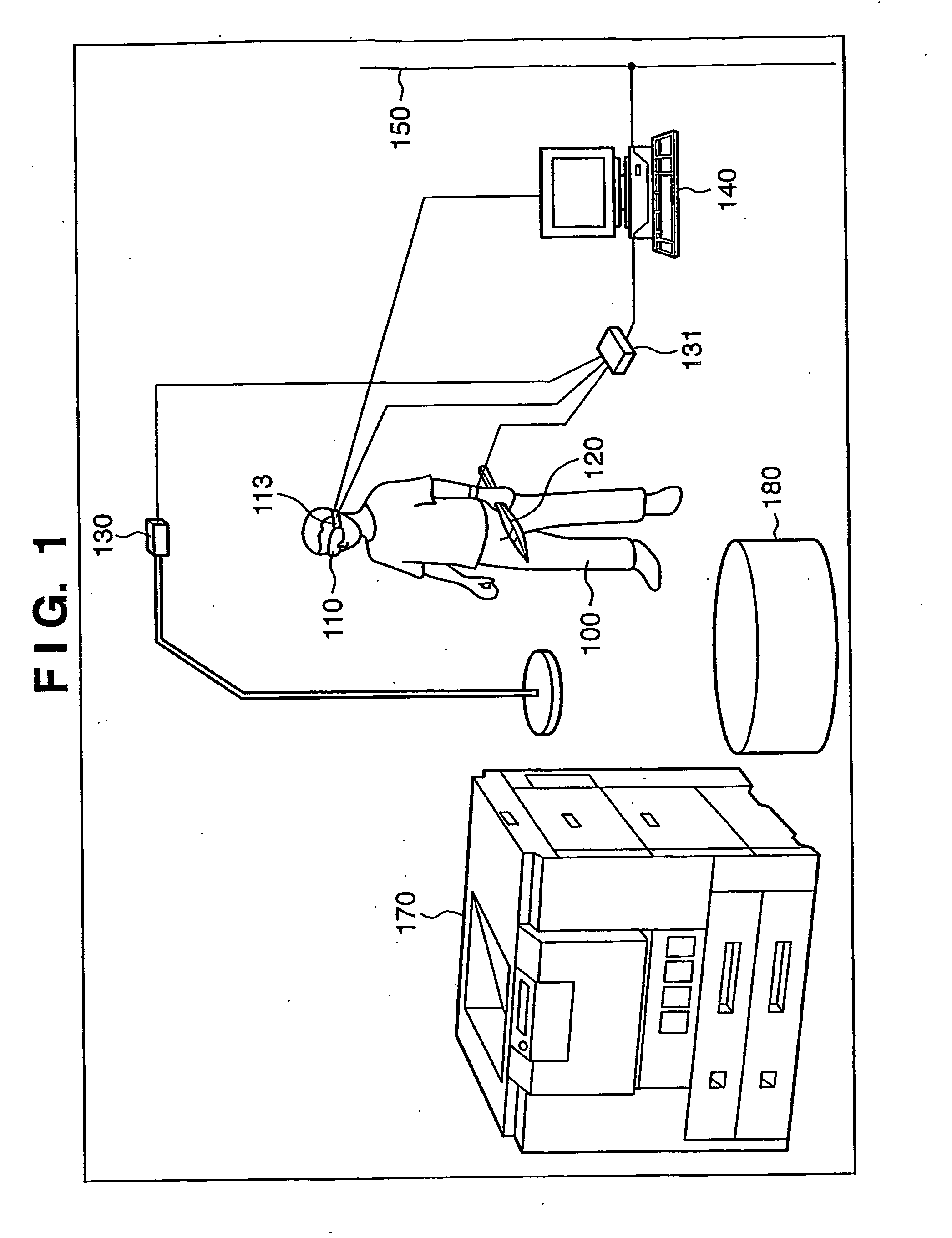
[0073]FIG. 1 is a view showing the outer appearance of the system according to this embodiment.
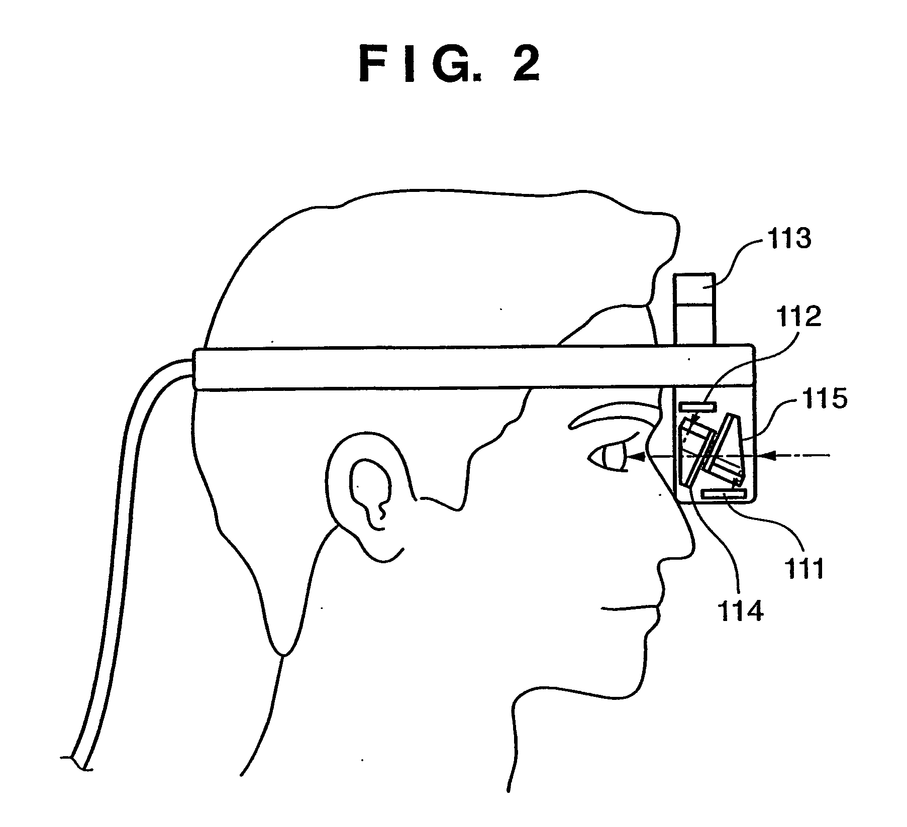
[0074] Referring to FIG. 1, reference numeral 100 denotes an observer. He / she wears an HMD (Head Mounted Display) 110 (to be described later) on the head and a stylus (pointing device) 120 (to be described later) in the hand (“wear” means both “hold in hand” and “attached to hand”).
[0075] A position / orientation sensor transmitter 130 generates a magnetic field. A position / orientation sensor receiver 121 provided in the stylus 120 and a position / orientation sensor receiver 113 provided on the HMD 110 measure the magnetic field intensities corresponding to th...
second embodiment
[0135] In this embodiment, the display position of a list image is changed, and display is turned on / off in addition to the first embodiment. The main thread of the second embodiment is the same as in the first embodiment (according to the flowchart shown in FIG. 4) except list image display processing in step S404.
[0136]FIG. 19 is a flowchart of list image display processing according to this embodiment, which is executed in step S404. Processing according to the flowchart shown in FIG. 19 is executed after the virtual object image is generated.
[0137] It is determined whether a mode to display a list image (assembly tree) is set (step S1901). This mode can be set by an operation unit 3104. Data representing the set mode is stored in a RAM 3102. Hence, in step S1901, it is determined by referring to this data whether the display mode or non-display mode is set. There are also various kinds of modes which can be set by the operation unit 3104, and data representing the set mode is ...
third embodiment
[0151] In this embodiment, a function of making the list image displayed in the first embodiment semitransparent is added.
[0152]FIG. 8 is a view showing a display example of a list image 801 having a completely transparent background and opaque characters. The characters may be hard to read depending on the background. However, when the list image shown in FIG. 8 is employed, images other than the list image are easier to see than the example shown in FIG. 7.
[0153]FIG. 20 is a flowchart of list image display processing according to this embodiment, which is executed in step S404. In this embodiment, the list image is a 3D virtual object, as in the first embodiment. However, it may be a 2D image, as in the second embodiment.
[0154] When a virtual object is present in the direction of line of sight of an observer 100, it is determined whether a mode to display a semitransparent list image is set (step S2010). This mode can be set by an operation unit 3104. Data representing the set ...
PUM
 Abstract
Description
Claims
Application Information