Super wide-angle panoramic imaging apparatus

a panoramic imaging and super wide-angle technology, applied in the field of panoramic image sensing, can solve the problems of affecting the image quality of the image, so as to achieve the effect of not losing significant image quality

Inactive Publication Date: 2003-08-26
REMOTEREALITY
View PDF16 Cites 167 Cited by
  • Summary
  • Abstract
  • Description
  • Claims
  • Application Information

AI Technical Summary

Benefits of technology

Another aspect of the present invention is a two mirror panoramic system that is substantially scalable, in that the size of all components and their relative positions can be scaled without significant loss of image quality.

Problems solved by technology

The lack of a single viewpoint introduces aberrations in pupils which manifests itself as uncorrectable geometric transformations (distortions).
But a lens, however wide angle it may be, is limited to a hemispherical field of view while still maintaining a single viewpoint, although it is physically challenging to design such wide-angle lenses.
However, these so-called fish eye lenses are significantly larger and more complex than conventional lenses, and suffer from severe geometric distortions and loss of resolution in the image over the field of view.
Moreover, the lack of a single reference point for the rays of light imaged by the lens disqualifies their usage in a large number of applications, described above.
Thus, of the known dioptric systems, those that seek to preserve a single viewpoint are limited to a narrow field of view.
A disadvantage of such systems is their light gathering ability which requires them to operate with lower F-numbers.
It is worthwhile mentioning here that while the sphere is an intuitive solution it is impractical because the focus is at the center of the sphere, and so is the cone for the reason that the focus is at the apex of the cone.
A disadvantage of the system is that the use of an aspheric surface results in residual field curvature.
However we have determined that mirrors with complex shapes produce confounding optical aberrations.
Moreover, even seemingly simple surfaces such as quadrics (surfaces of revolution of planar 2nd order algebraic curves) can produce complex optical aberrations.
While these systems are panoramic in nature, none seek to preserve a single reference viewpoint, resulting in severe geometric distortion in the image captured off the primary reflector.
The complexity of these systems lies in their relay objective lenses, which are required to compensate for such severe spherical aberrations.
These systems also exhibit complex field curvature, by far the most difficult aberration to correct.
As a result, these systems have high F-numbers resulting in additional complexity in the relay objective lenses.
Additionally, the use of strong elements in the astigmatism correction lens introduces deleterious amounts of spherical aberration (lack of a single reference viewpoint) and coma into the final image.
The use of two convex mirrors causes the system to exhibit severe field curvature, hence the need for a complex relay objective lens.
Since the primary mirror is concave, the field of view in the vertical plane is limited to 180.degree..
Investigation has shown that no effort was apparently made to make the two mirrors confocal and further, it is evident that the use of a sphere or oblate spheroid in conjunction with a hyperboloid, results in severe spherical aberration of pupils.
Doing so severely restricts the field of view due to vignetting of the scene by the secondary reflector, typically to less than 45 degrees above and below the horizon.
This results in severe spherical aberration in pupils that manifests itself as uncorrectable geometric distortion in the captured image.
Those systems that do maintain a single viewpoint are limited either in their ability to perform under varying light conditions and F-numbers due to significant field curvature that remains uncorrected, or in their vertical field of view due to vignetting by optical components.
Further, the use of objective lenses for correcting above mentioned spherical aberration and field curvature results in chromatic aberrations.
Furthermore, these objective lenses tend to be highly complex and expensive.

Method used


Image

  • Super wide-angle panoramic imaging apparatus
  • Super wide-angle panoramic imaging apparatus
  • Super wide-angle panoramic imaging apparatus

Examples


example three

6.3. Example Three

FIG. 7 illustrates a third exemplary arrangement of the present invention wherein the primary reflector was hyperboloidal in shape and the secondary reflector was spherical, hence ellipsoidal. Field of view of this system was 220 degrees in a vertical plane, the F number was 2.8, the focal length was -0.95 mm, the image diameter was 3.6, which fits to a one third inch (0.85 cm) CCD. The microprojection relay lens had a focal length of 6.25 mm, a back focal length of 8.245 mm, and a distance from the C.sub.1 vertex of 9 mm. Once again, as in the earlier arrangement, the position of the secondary reflector was between the far focus of the primary reflector and the apex of the primary reflector. In such an arrangement, the spherical aberration in pupils was minimal as can be seen from the graphs of saggital and tangential field curvature from FIG. 8(a). The graphs of S and T closely follow each other, indicating a compact caustic of viewpoints. FIG. 8(b) shows a graph...

first embodiment

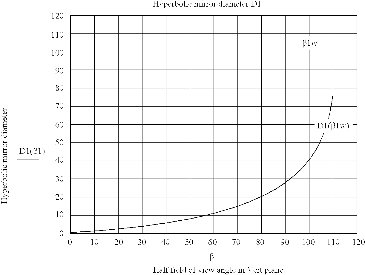
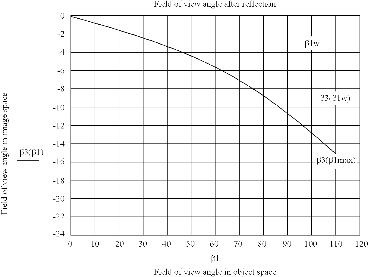
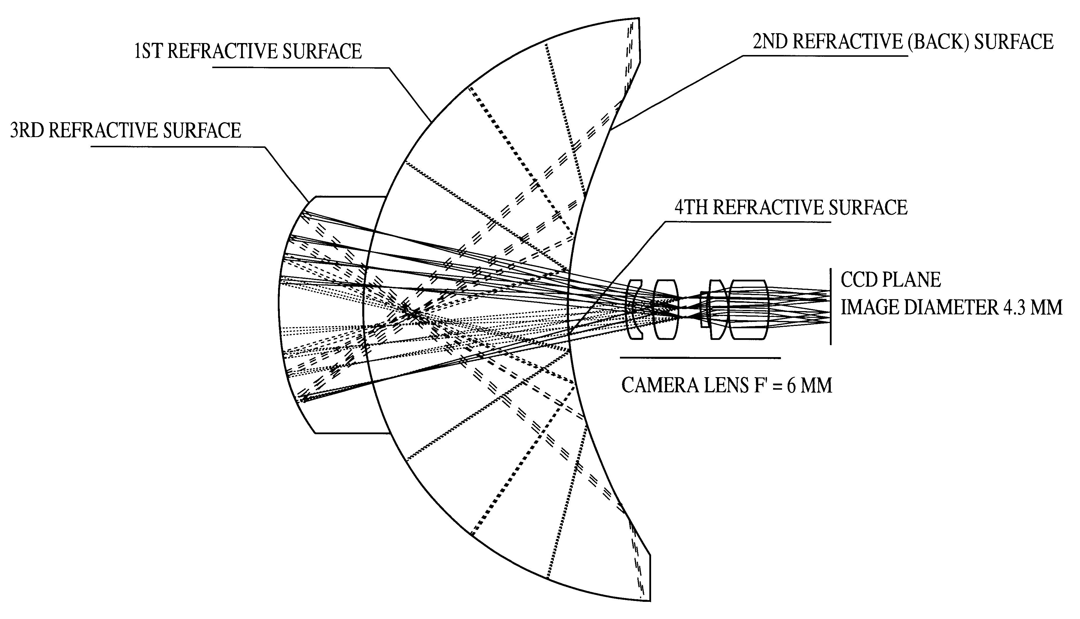
FIGS. 10, 11(a)(b) and 12 illustrate a fourth exemplary embodiment that was similar to the first embodiment in FIG. 1. The primary and secondary mirrors were once again convex hyperboloidal and concave ellipsoidal, respectively--and had almost equal radii of curvature at the vertexes. Field of view of the system was 260 degrees in a vertical plane, focal length was -0.6 mm, F number was 2.8, and image diameter was 3.6 mm. Relay focal length was 10.25 mm, its back focal length was 13.2 mm. Image quality was comparable (300 lp / mm under 40% of contrast), as for the second and third examples. From FIG. 11(a) can be seen the very high level of the astigmatism and field curvature correction. Image flatness is in the range of from about 4 to about 5 micrometers. This kind of image quality correction was achieved without introduction of higher order aspherical surfaces for the two mirrors. On the other hand, the first hyperbolic mirror diameter was about 135.5 mm, i.e., about three times th...

example five

6.5. Example Five

FIG. 13 shows a fifth exemplary arrangement in which the relay objective was now a Double-Gaussian type of lens, indicated by 5. The rest of the arrangement is similar to that in FIG. 1, in that the primary mirror was hyperboloidal in shape, the secondary reflector was ellipsoidal in shape and the two conics were strictly confocal. Again, in this arrangement, the caustic of viewpoints was substantially a single viewpoint and hence the system had a single viewpoint of reference.


PUM


Abstract

A system for capturing super wide-angle panoramic images. In particular, a two-reflector system is disclosed which is substantially self-correcting in which optical aberrations are substantially eliminated, such as field curvature, astigmatism and the like. Moreover, the super wide-angle panoramic imaging apparatus of the invention captures a super-wide field of view from a substantially single reference viewpoint. The invention provides a substantially compact viewpoint, while also having a substantially flat and stigmatic image plane, in the context of a super wide-angle panoramic system. Devices and methods for capturing panoramic images of super wide-angle scenes are provided. In a particular embodiment of the invention, two reflectors are provided (e.g., one a hyperboloidal mirror, the other a concave ellipsoidal or spherical mirror), a relay system (e.g., optics such as a mirror, a lens, a pinhole and the like) and an image sensor (e.g., an electronic photo-sensor, a film and the like).

Description

1. FIELD OF THE INVENTIONThis invention relates to panoramic image sensing of a super wide-angle field of view, and in particular, it relates to such image sensing using a two-mirror subsystem that is substantially self-corrected. The term "panoramic" means a 360.degree. field of view in a horizontal plane while the term "super wide-angle" means a 120.degree. or larger field of view in a vertical plane. Preferably, the field of view in a vertical plane is greater than about 1800. More preferably, it is greater than about 200.degree.. And, for the desired apparatus, most preferably, it is greater than about 260.degree..2. BACKGROUND OF THE INVENTIONA perspective imaging system collects rays of light from the scene that pass through a single point of reference and projects them onto a sensing element such as film or a charge coupled device (CCD). The single point of reference in the perspective imaging system is known as the viewpoint of the system. Yamazawa et al., "Omnidirectional I...

Claims


Application Information

Patent Timeline
Patent Type & Authority Patents(United States)
IPC IPC(8): G02B17/06G02B13/06G02B17/00G02B17/08G03B37/00
CPCG02B13/06G02B17/061G02B17/0808
Inventor TRUBKO, SERGEYPERI, VENKATA N.NAYAR, SHREE K.KOREIN, JAMES
Owner REMOTEREALITY
Why Eureka
Try Eureka