Long-wave long-focus uncooled thermalization-free infrared optical system

An infrared optical system and optical system technology, which is applied in the field of long-wavelength coke uncooled athermal infrared optical system, can solve the problems that the infrared optical system is particularly affected, the optical-mechanical structure is complicated, and the focus speed is limited, and the improvement can be achieved. Imaging quality, system compactness, and weight reduction effects

Active Publication Date: 2011-04-27
LUOYANG INST OF ELECTRO OPTICAL EQUIP OF AVIC
View PDF3 Cites 13 Cited by
  • Summary
  • Abstract
  • Description
  • Claims
  • Application Information

AI Technical Summary

Problems solved by technology

[0002] The temperature range of the working environment of most airborne military optical instruments is relatively large. When the temperature changes, the curvature, thickness, and refractive index of the optical elements will change. Because the temperature coefficient of refractive index of infrared optical materials is one or two larger than that of visible light materials Therefore, the impact of environmental temperature changes on the infrared optical system is particularly serious, so an active or passive compensation mechanism must be added to the infrared imaging system to compensate for the system performance degradation caused by the movement of the image plane caused by temperature changes
Such a design makes the optical-mechanical structure complex, and the focusing speed is limited by the mechanism, so it is not suitable for situations that require fast focusing in high and low temperature environments.

Method used


Image

  • Long-wave long-focus uncooled thermalization-free infrared optical system
  • Long-wave long-focus uncooled thermalization-free infrared optical system
  • Long-wave long-focus uncooled thermalization-free infrared optical system

Examples


Embodiment Construction

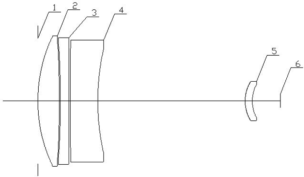
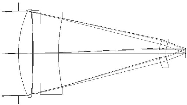
[0018] The system diagram of the embodiment of the long-wavelength focal uncooled and non-thermal infrared optical system of the present invention is as follows figure 1 As shown, the optical system has an aperture stop 1, a first lens 2, a second lens 3, a third lens 4, a fourth lens 5, and a detector image surface 6 arranged coaxially along the light incident direction in sequence, the first lens 2, The second lens 3, the third lens 4, and the fourth lens 5 adopt a positive-negative-negative-positive symmetrical structure, and their optical materials are respectively zinc selenide, single crystal germanium, zinc sulfide, and single crystal germanium. The first lens 2, the second lens 3, and the third lens 4 form a convergent group, which is mainly used to correct primary aberrations such as spherical aberration and coma, and correct primary chromatic aberration. The fourth lens 5 further narrows the light beam, and is mainly used to correct positional chromatic aberration and ...


PUM


Abstract

The invention relates to a long-wave long-focus uncooled thermalization-free infrared optical system, belonging to the technical field of optics. The optical system comprises an aperture diaphragm, a first lens, a second lens, a third lens and a fourth lens which are sequentially and axially arranged along a light incident direction, wherein the first lens, the second lens and the third lens forma converging group used for correcting primary aberration, the lenses are in a positive-negative-negative-positive symmetrical structure, the first face of the second lens is a rotating and symmetrical diffractive face, and thermal expansion coefficients of the optical elements and the structural materials of the four lens and the intervals and the curvature radii of the four lenses all satisfy aformula. By utilizing different temperature characteristics and linear expansion coefficients of various optical materials and combining with a lens cone material, the self adaptation to the environment is realized to realize a thermalization-free function, which can effectively simplify the structure of an optical machine, reduce system weight, shorten system volume and improve the imaging quality of the optical system in different temperature environments.

Description

Technical field [0001] The invention relates to a long-wavelength focal non-cooling and non-heating infrared optical system, belonging to the field of optical technology. Background technique [0002] Most airborne military optical instruments have a relatively wide range of temperature changes in the working environment. When the temperature changes, the curvature, thickness, and refractive index of the optical components will change. Because the temperature coefficient of refractive index of infrared optical materials is one or two larger than that of visible light materials Therefore, the influence of environmental temperature changes on the infrared optical system is particularly serious. Therefore, an active or passive compensation mechanism must be added to the infrared imaging system to compensate for the degradation of system performance caused by the image surface movement caused by temperature changes. Such a design complicates the structure of the optical machine, and ...

Claims


Application Information

Patent Timeline
Patent Type & Authority Applications(China)
IPC IPC(8): G02B27/00G02B1/02G02B7/02G02B3/08G02B3/02
Inventor 王希军
Owner LUOYANG INST OF ELECTRO OPTICAL EQUIP OF AVIC
Why Eureka
Try Eureka