Corrector for axial and off-axial beam paths

a particleoptical system and correction technology, applied in the field of particleoptical correction technology, can solve the problems of geometrical image aberration, aperture aberration, complicated resolution limit of half a wavelength, etc., and achieve the effect of eliminating the astigmatism of third order

Inactive Publication Date: 2010-10-05
CEOS CORRECTED ELECTRON OPTICAL SYST
View PDF6 Cites 14 Cited by
  • Summary
  • Abstract
  • Description
  • Claims
  • Application Information

AI Technical Summary

Benefits of technology

[0013]The object is achieved in accordance with the invention in that a central multipole element disposed in the center plane generates an octupole field for eliminating the astigmatism of third order.
[0014]Due to the fact that the octupole field of the central multipole field also eliminates the astigmatism of third order, the corrector can largely eliminate the aberrations of the objective lens, of other lenses, and also the aberrations caused by itself up to higher orders, or even prevent them from being generated through corresponding adjustment of the above-mentioned quadrupole and octupole fields. Further improvements can be obtained by means of further embodiments that can be derived from the dependent claims.
[0022]The basic idea of the invention consists in eliminating this latter aberration through arrangement of a multipole element for generating an octupole field, wherein the arrangement in the center plane in which both off-axial fundamental paths xγ and yδ cross the axis, ensures that this multipole element itself does not cause any new off-axial aberrations.
[0023]Further developments of the corrector eliminate further aberrations of higher orders.
[0029]In order to also correct the above-mentioned aperture aberrations of fifth order or a correlated, although small, radial coma of third order or reduce them to a tolerable degree, the invention proposes to allocate two transfer lenses, formed as round lenses, to the corrector on the objective side, the field setting of which can eliminate the aperture aberrations of fifth order and / or radial coma of third order or reduce them to a tolerable degree.
[0034]The corrector is mainly used in transmission electron microscopes, in which beams of a relatively large diameter are used, and for this reason, the correction of the off-axial beam path is also very important. The degree of aberration elimination or aberration toleration thereby depends on the desired image resolution or the desired image size. For high image resolution, aberrations must be eliminated to a larger degree, however, with a smaller image size. For large image sizes, however, residual aberrations and thereby a smaller resolution can be tolerated.

Problems solved by technology

Achieving the theoretically possible resolution limit of half a wavelength is complicated by the fact that the lenses that are used operate with magnetic or electric fields and exhibit numerous lens aberrations.
The geometrical image aberrations are mainly due to inaccurate imaging by the electromagnetic fields which must obey the Laplace equation.
This produces aperture aberrations because the focal length of the outer lens zones is smaller than that of the inner lens zones.
A further source of aberrations results from the fact that the lenses are not completely symmetrical and therefore the strength of the lenses differs in two directions perpendicular to the optical axis.
There are, however, further image aberrations, the cause of which is not always known.
This corrector, however, was not further examined, since it is disadvantageous compared to other proposals made therein.
In particular, the astigmatism of third order would be difficult to eliminate with the corrector of the above-mentioned type, thereby unavoidably causing aberrations of higher order.

Method used


Image

  • Corrector for axial and off-axial beam paths
  • Corrector for axial and off-axial beam paths
  • Corrector for axial and off-axial beam paths

Examples


Embodiment Construction

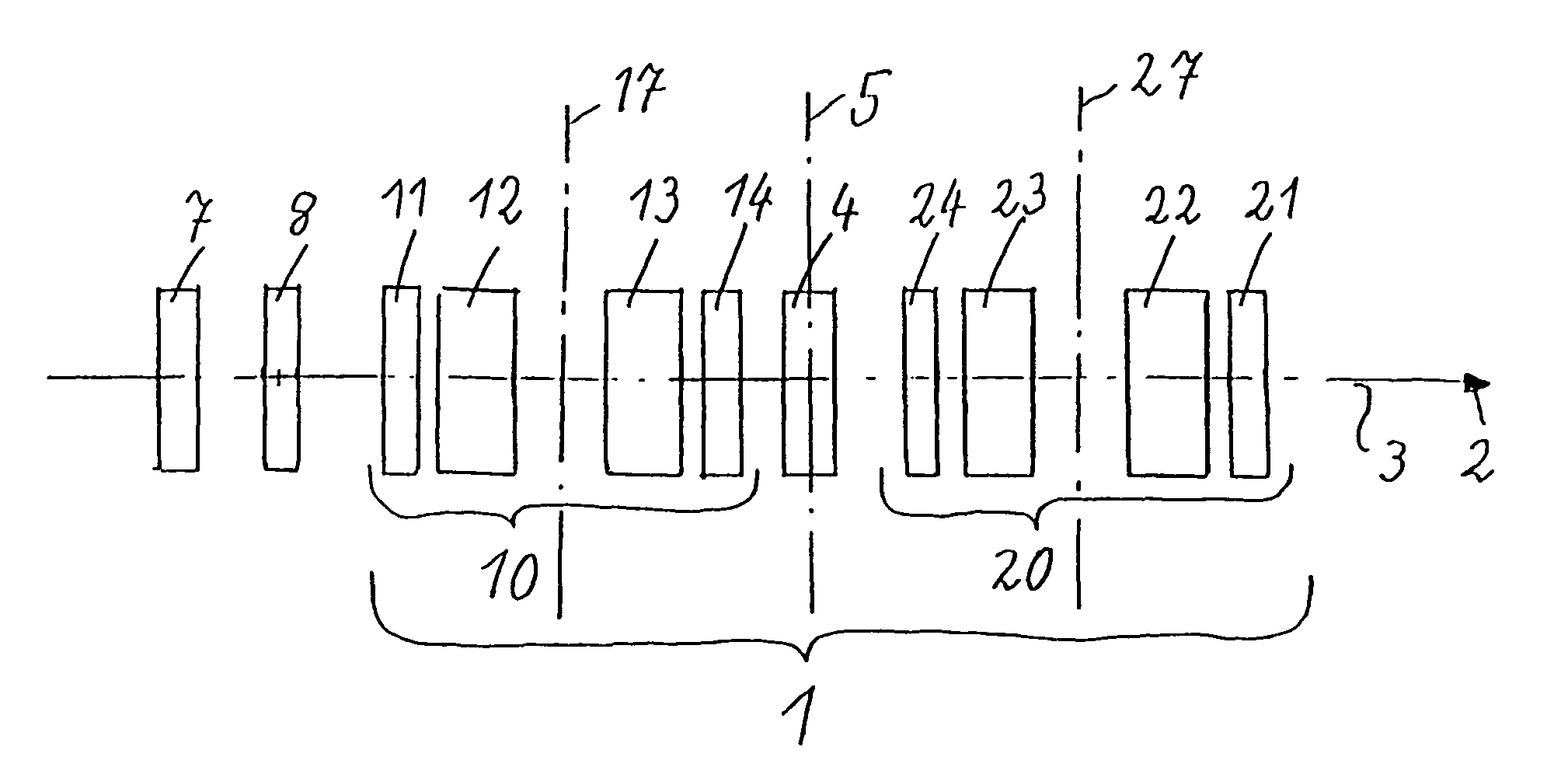
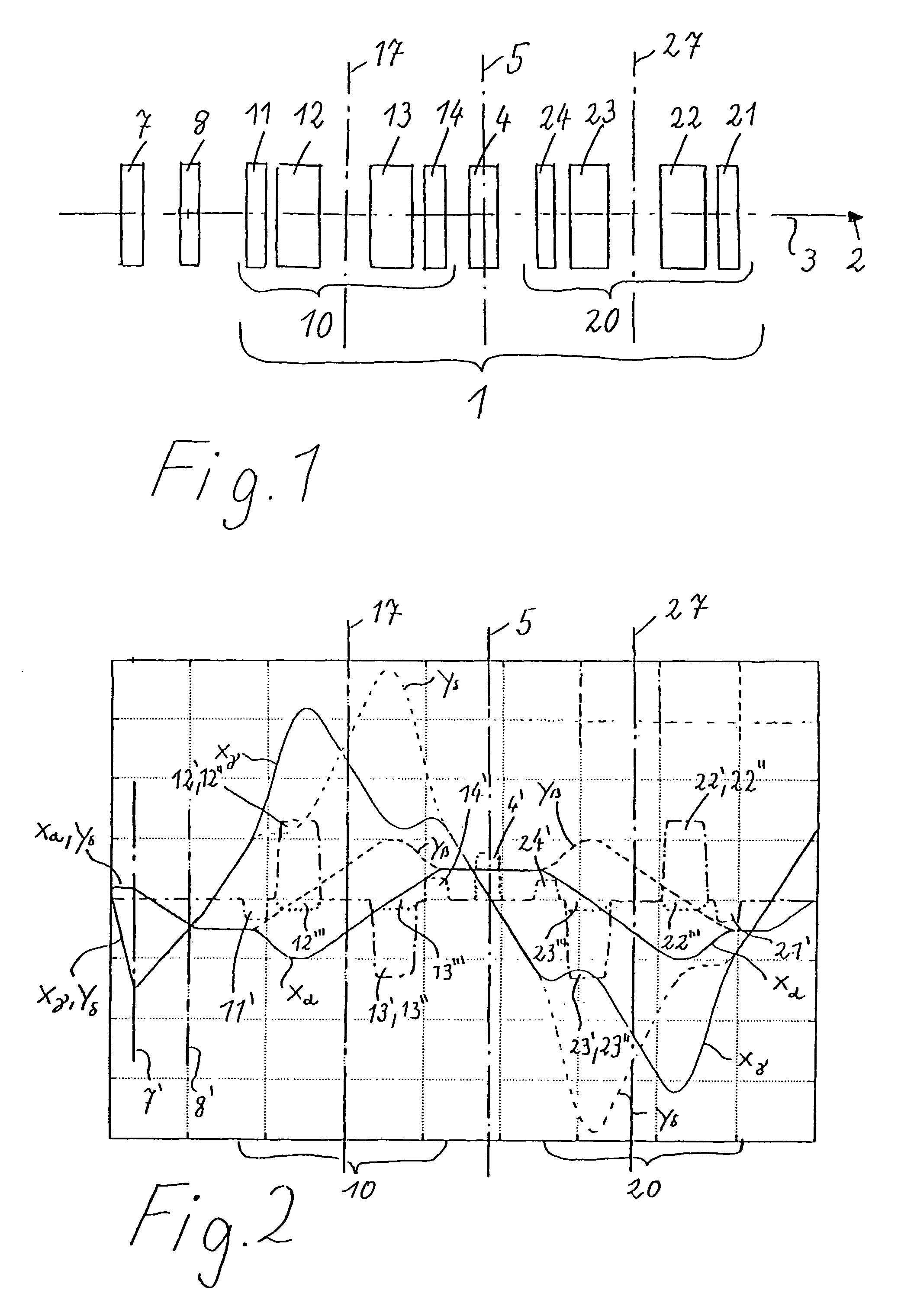
[0043]All illustrations are shown in accordance with the following system:

[0044]Identical reference numerals always show identical parts, field dependences etc. All reference numerals between 11 and 19 thereby relate to the first correction piece 10, and all reference numerals between 21 and 28 relate to the second correction piece 20. The correction piece 10 has multipole elements 11, 12, 13, 14, and the correction piece 20 has multipole elements 21, 22, 23, 24. The multipole elements with the same final digits have the same construction and generate identical fields with respect to the basic functions of the invention in accordance with FIG. 2. The reverse order of the reference numerals shown in FIG. 1, i.e. first 11, second 12, third 13 and fourth 14 multipole elements of the correction piece 10, and first 24, second 23, third 22, and fourth 21 multipole elements of the correction piece 20, symbolizes the symmetry with respect to the center plane 5, with reverse order of the mul...


PUM


Abstract

A corrector (1) for the axial and off-axial beam path of a particle-optical system, comprises a first (10) and a second (20) correction piece, which are disposed one behind the other in the beam path (2) on an optical axis (3). Each correction piece (10, 20) comprises four successive multipole elements (11, 12, 13, 14; 24, 23, 22, 21) disposed symmetrically with respect to a center plane (5) and with the following fields: wherein the first (11; 24) and the fourth (14; 21) multipole elements of the multipole elements (11, 12, 13, 14; 24, 23, 22, 21) are used to generate quadrupole fields (11′, 14′; 24′, 21′) and the second (12; 23) and third (13; 22) are used to generate octupole fields (12′″, 13′″; 23′″,22′″) and quadrupole fields (12′, 13′; 23′,22′), wherein the latter are superposed magnetic (12′, 13′; 23′, 22′) and electric fields (12″, 13″; 23″, 22″), wherein the quadrupole fields (11′, 12′, 13′, 14′; 24′, 23′, 22′, 21′) of all four multipole elements (11, 12, 13, 14; 24, 23, 22,21) are rotated from one to the next through 90°. An astigmatism of third order is corrected by a central multipole element disposed in the center plane and generating an octupole field.

Description

[0001]This application claims Paris Convention priority of DE 10 2007 058 443.3 filed Dec. 5, 2007 the complete disclosure of which is hereby incorporated by reference.BACKGROUND OF THE INVENTION[0002]The invention concerns a corrector for axial and off-axial beam paths of a particle-optical system, comprising a first and a second correction piece, which are successively disposed in the beam path on an optical axis, wherein each correction piece comprises four successive multipole elements disposed symmetrically with respect to a center plane and with the following fields, wherein the first and the fourth multipole elements are used to generate quadrupole fields, and the second and the third multipole elements are used to generate octupole fields and quadrupole fields, wherein the latter are superposed magnetic and electric fields, and wherein the quadrupole fields of all four multipole elements are successively rotated from one to the other through 90°, such that chromatic aberrati...

Claims


Application Information

Patent Timeline
Patent Type & Authority Patents(United States)
IPC IPC(8): H01J37/153H01J37/26G21K1/08
CPCH01J37/153H01J37/26H01J2237/1532H01J2237/1534
Inventor ZACH, JOACHIMROSE, HARALD
Owner CEOS CORRECTED ELECTRON OPTICAL SYST
Why Eureka
Try Eureka