A laser beam astigmatism compensation method and laser processing system

A laser processing and laser beam technology, applied in metal processing equipment, laser welding equipment, manufacturing tools, etc., can solve problems such as inconsistent line width and depth, affecting the quality of laser processing, etc., to reduce processing costs, improve processing effects, and design The effect of improved consistency of line width and depth

Active Publication Date: 2022-04-15
WUHAN HGLASER ENG CO LTD
View PDF0 Cites 0 Cited by
  • Summary
  • Abstract
  • Description
  • Claims
  • Application Information

AI Technical Summary

Problems solved by technology

figure 1 It is a schematic diagram of astigmatism in laser processing and the shape of the focused spot showing astigmatism. If the laser beam has obvious astigmatism, when the laser beam is focused, although the focused spot is a circle, it is in a defocused state. The bottom will be an obvious elliptical spot. Using such a spot to process the material out of focus will lead to inconsistent line width and depth when scribing in different directions, which will seriously affect the quality of laser processing.

Method used


Image

  • A laser beam astigmatism compensation method and laser processing system
  • A laser beam astigmatism compensation method and laser processing system
  • A laser beam astigmatism compensation method and laser processing system

Examples


Embodiment 1

[0036] This embodiment discloses a laser beam astigmatism compensation method, including the following steps:

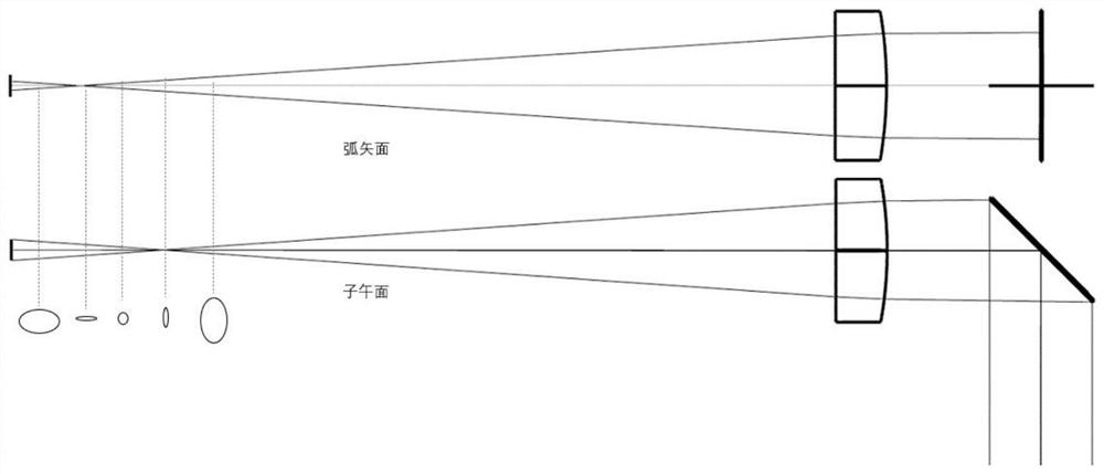
[0037] An astigmatism compensation device is added to the external optical path of the laser processing system, and the astigmatism is generated after the laser beam passes through the astigmatism compensation device;

[0038] Adjust the rotation angle of the optical elements in the astigmatism compensation device, change the size and direction of the astigmatism generated by the astigmatism compensation device, so that the astigmatism generated by the astigmatism compensation device is equal to the astigmatism of the original laser processing system and opposite in direction. The astigmatism of the whole laser processing system is reversely compensated.

[0039] The patent can manually adjust the rotation angle of the astigmatism compensation optical element, and can also automatically adjust the rotation angle of the astigmatism compensation optical element. In th...

Embodiment 2

[0061] Figure 8 What is shown is a schematic diagram of a common laser processing optical path application debugging. This embodiment discloses a laser processing system, including a laser 1, a vibrating mirror 3, a field lens 4, and an astigmatism compensation device 5. The laser 1 is used for generate and emit laser beams;

[0062] The vibrating mirror 3 is used to receive the laser beam, and the motor drives the mirror to swing to change the processing path of the laser beam;

[0063] The field lens 4 is used to focus the laser beam passing through the galvanometer onto the surface of the sample to be processed for processing;

[0064] The astigmatism compensation device 5 is located on the optical path before or after focusing, and the astigmatism compensation device is used to generate the reverse astigmatism equivalent to the astigmatism of the original laser processing system, and compensate the laser and laser in the laser processing system. Astigmatism formed compr...


PUM


Abstract

The invention discloses a laser beam astigmatism compensation method and a laser processing system. By adding an astigmatism compensation device in the external optical path of the laser processing system, the astigmatism is generated after the laser beam passes through the astigmatism compensation device; the astigmatism compensation device is adjusted The rotation angle of the optical components in the astigmatism compensation device changes the size and direction of the astigmatism, so that the astigmatism generated by the astigmatism compensation device is equal to the astigmatism of the original laser processing system, and the direction is opposite. Astigmatism is reverse compensated. The present invention can reduce the astigmatism of the laser beam that finally reaches the processing table, so that both the focused and defocused spots are a circular spot, and the consistency of the width and depth of the scribe line in any direction is improved when laser processing is performed in the defocused state. Eliminating the astigmatism problem of the laser beam can significantly improve the quality of laser processing, improve the processing effect, improve the yield rate, and reduce the processing cost.

Description

technical field [0001] The invention relates to the technical field of laser processing, in particular to a laser beam astigmatism compensation method and a laser processing system. Background technique [0002] With the continuous development of laser processing technology, its application scope is getting wider and wider, and the corresponding laser processing technology effect has higher and higher requirements on the quality of the laser beam itself. The laser beam is generated by the laser and the designed external optical path is used to process the sample. The common optical components in the external optical path are total reflection mirror, beam expander, beam splitting element, vibrating mirror, field mirror, etc. During the transmission of the laser, due to the optical components Some defects in the manufacturing process or the installation structure process, such as surface shape and coating quality, cannot reach the ideal state, which will have an adverse effect...

Claims


Application Information

Patent Timeline
Patent Type & Authority Patents(China)
IPC IPC(8): B23K26/064B23K26/073B23K26/70
CPCB23K26/064B23K26/0736B23K26/702
Inventor 王雪辉冯新康雷桂明喻浩王建刚
Owner WUHAN HGLASER ENG CO LTD
Why Eureka
Try Eureka