Interference-free tool path generation method in machining of transitional surfaces by flat-end milling cutter

A flat end mill and transition surface technology, applied in the field of curved surface processing, can solve the problems of reduced processing efficiency, poor surface smoothness, low processing efficiency of ball-end cutters, etc., and achieve the effect of improving processing efficiency

Inactive Publication Date: 2014-04-23
HUAZHONG UNIV OF SCI & TECH
View PDF6 Cites 44 Cited by
  • Summary
  • Abstract
  • Description
  • Claims
  • Application Information

AI Technical Summary

Problems solved by technology

[0003] At present, most of the processing methods for such transitional surfaces are three-axis CNC machining based on ball-end milling cutters. Since the effective cutting radius of each point of the ball-end milling cutter is the same, the cutting speed varies with the position of the tool contact on the blade. , the cutting speed at the end of the ball-end cutter is zero, the cutting performance is poor, the smoothness of the curved surface is also poor, the processing tool paths are very dense, and the processing efficiency of the ball-end cutter is low
At present, the main CAM commercial software such as UG, PowerMILL, etc. carry out tool path planning for surface processing, and the output tool position files cannot guarantee no interference. Instead, the interference checking part is put into the processing simulation for processing. If there is interference, it must be restarted. Adjusting or re-planning the tool trajectory generally requires multiple iterations to obtain the non-interference tool trajectory, which greatly reduces the processing efficiency and increases the processing cost

Method used


Image

  • Interference-free tool path generation method in machining of transitional surfaces by flat-end milling cutter
  • Interference-free tool path generation method in machining of transitional surfaces by flat-end milling cutter
  • Interference-free tool path generation method in machining of transitional surfaces by flat-end milling cutter

Examples


Embodiment Construction

[0047] In order to make the object, technical solution and advantages of the present invention clearer, the present invention will be further described in detail below in conjunction with the accompanying drawings. The description herein is only used to explain the present invention when referring to specific examples, and does not limit the present invention.

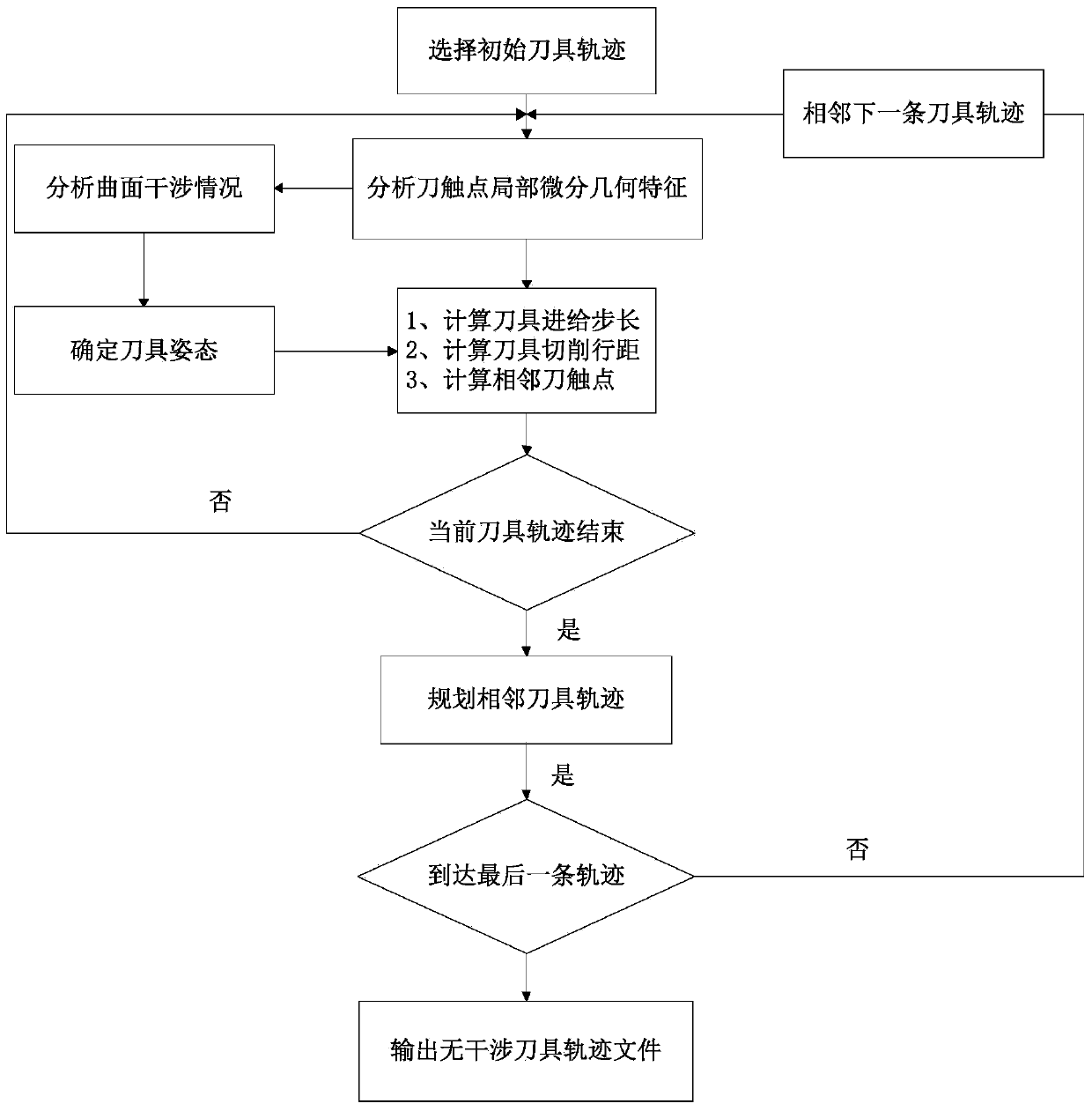
[0048] The flow chart of a method for generating a non-interference tool trajectory for machining a transition surface with a flat end mill in an embodiment of the present invention is as follows figure 1 shown.

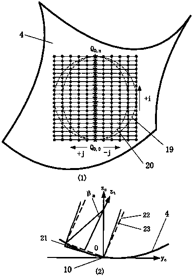
[0049] First, an initial machining tool trajectory is selected on the transition surface, and the tool is processed along the ridge line of the transition surface, and the current tool contact is calculated on this path, and the local differential geometric characteristics of the tool contact are analyzed based on the differential geometry theory, mainly including the transition The local relevant data of th...


PUM


Abstract

The invention discloses a method for generating interference-free flat-end milling cutter process path along the ridge direction of transitional surfaces. The method comprises the following steps: (1) initial machining tool path is set, a tool is processing along the ridges of transitional surfaces, a current tool contact is calculated to obtain effective curvature of the machining tool at the tool contact; (2) curvature interference analysis of transitional surface machining is carried out according to the effective curvature of the machining tool at the tool contact, tool bottom interference is analyzed, and the angle of the tool is deflected at the tool contact to obtain interference-free tool posture; (3) parameter calculation is carried out on the adjusted tool path so as to obtain step-length and cut row distance; and (4) adjacent tool path lines are calculated, including calculation of adjacent tool contacts and calculation of tool location data, and interference-free tool path is finally obtained. By the method, automatic planning of interference-free tool path can be realized; large cut row distance is obtained; cutting efficiency is high; machining surface roughness is low; surface fairness is good; and problems of low cutting efficiency, poor machining surface quality and the like by machining of a ball-end milling cutter are solved.

Description

technical field [0001] The invention belongs to the technical field of curved surface processing, and in particular relates to a method for generating tool tracks, which is suitable for numerical control processing of transitional curved surfaces. Background technique [0002] Some special transition surfaces are often involved in the design of curved surface products such as automobile bodies and aerospace vehicles, which play the role of beautiful decoration or enhanced rigidity to meet the requirements of product shape design. These special transition surfaces are divided into two types: equal-radius transition surfaces and variable-radius transition surfaces according to whether the curvature radii of each cross-section along the ridge are equal. The key to the processing of such transition surfaces lies in the generation of non-interfering tool paths in the transition area of ​​the surface. . Compared with three-axis machining, five-axis machining has more advantages d...

Claims


Application Information

Patent Timeline
Patent Type & Authority Applications(China)
IPC IPC(8): G05B19/19
Inventor 喻道远张永杰邵新宇蒋勇平邹志华林文文张三强周小强于岚旭姜昕亚
Owner HUAZHONG UNIV OF SCI & TECH
Why Eureka
Try Eureka