Retaining Device for Tube Member

Inactive Publication Date: 2011-05-05
HUNG CHUNG TIEN INT
View PDF23 Cites 6 Cited by
  • Summary
  • Abstract
  • Description
  • Claims
  • Application Information

AI Technical Summary

Benefits of technology

Secondary object of the present invention is to provide a retaining device for a tube member that can apply a retaining force in circumferential direction to retain a grip on the tube member securely, and when the retaining device, the tube member, and the grip are connected together, an inner end of the retaining device contacts with an oute

Problems solved by technology

However, a certain portion of the external fence of the handlebar where is biased against by a distal end of the force bolt generates stress to cause a deformation on the external fence of the handlebar.
Moreover, a nut end of the force bolt exposes outside due to the metal engaging is thin, having a poor aesthetics appearance and injuring user's hands easily.
Another conventional retaining device includes a locking bolt locked on an opening of an elongated gap around the metal engaging m

Method used


Image

  • Retaining Device for Tube Member
  • Retaining Device for Tube Member
  • Retaining Device for Tube Member

Examples


Example

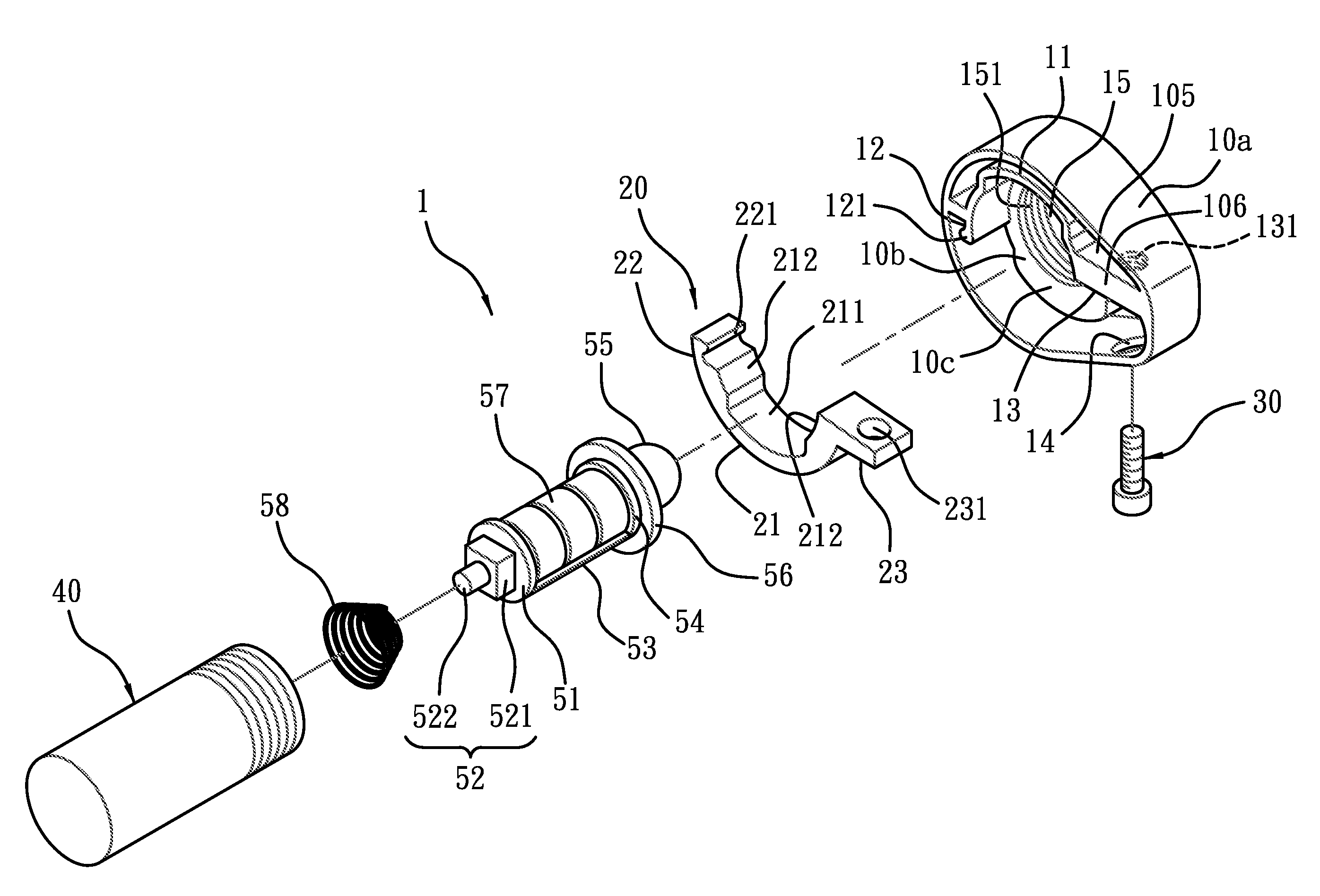
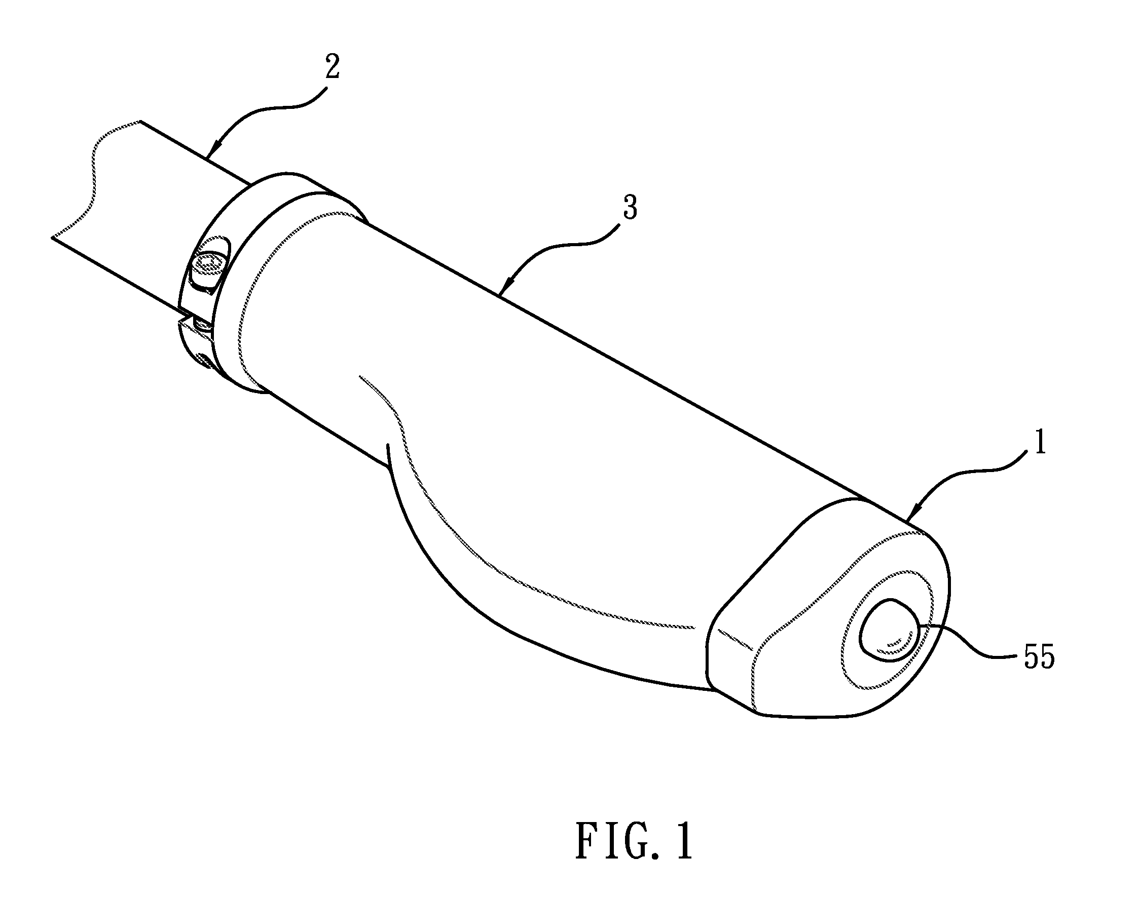
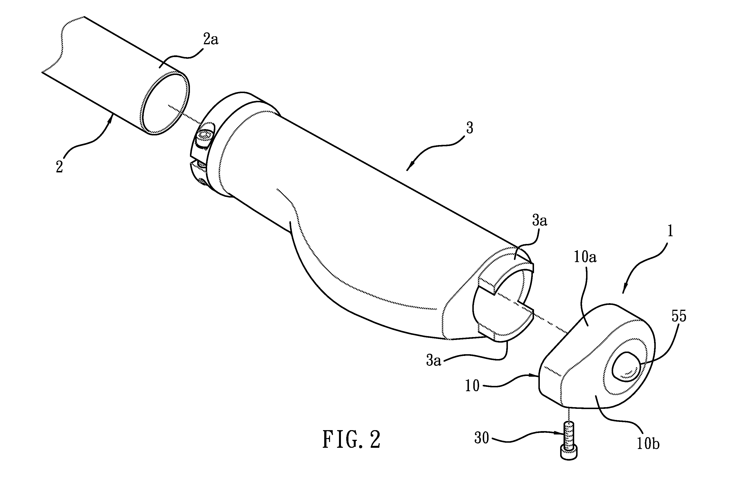
Referring to FIGS. 1-4, a retaining device 1 for a tube member according to a first embodiment of the present invention is used to retain a grip 3 on the tube member 2 and emit a warning light, wherein the tube member 2 is a handlebar of a bicycle, and the grip 3 includes two positioning projections 3a extending outward form an outer side thereof. The retaining device 1 comprises a body 10, a movable retaining member 20, a locking element 30, a housing 40, and a warning unit 50.

The body 10, as shown in FIG. 5, includes a peripheral fringe 10a and a side fringe 10b connected with each other to define a receiving space 10c, the receiving space 10c includes a first side 101 and a second side 102, the peripheral fringe 10a includes a first engaging portion 11 defined on a predetermined position thereof relative to the first side 101, and includes a first connecting portion 12 and a fixed portion 13 connected with two ends of the first engaging portion 11 respectively.

The peripheral frin...

Example

With reference to FIGS. 8 and 9, a difference of a retaining device according to a second embodiment of the present invention from that of the first embodiment comprises a body 10 including a peripheral fringe 10a, and the peripheral fringe 10a including a grip 16 integrally extending therefrom or coupled thereon, wherein the retaining device 1 of the second embodiment is designed in a different shape from that of the first embodiment, and a length of the grip 16 is different from that of the first embodiment so that when the retaining device 1 is installed on the tube member 2 of the handlebar of the bicycle, the retaining device 1 with the grip 16 is used as an auxiliary handle so that the user maintains different postures based on requirement.

Example

With reference to FIG. 10, a difference of a retaining device according to a third embodiment of the present invention from that of the first embodiment comprises a body 10 including a side fringe 10b, and the side fringe 10b is a closed surface, the retaining device is not provided with the housing 40 and the warning unit 50 of the first embodiment, and the trench 15 is not necessary in the third embodiment, hence when the retaining device 1 is installed on a tube member 2, the side fringe 10b is used as a closed retaining device 1 and an end plug.


PUM


Abstract

A retaining device for a tube member contains a body including a peripheral fringe and a side fringe connected together to define a receiving space, the receiving space including a first and a second sides, the peripheral fringe including a first engaging portion defined thereon, including a first connecting portion and a fixed portion connected with two ends of the first engaging portion respectively; a movable retaining member installed in the receiving space, and including a second engaging portion, and including a second connecting portion and a movable portion connected with two ends of the second engaging portion respectively, the second connecting portion being used to connect with the first connecting portion of the body; a locking element being used to force the moving portion toward the fixed portion of the body so that the external fence is retained tightly between the first locking fences and the locking fences.

Description

BACKGROUND OF THE INVENTION1. Field of the InventionThe present invention relates to a retaining device for a tube member.2. Description of the Prior ArtA conventional retaining device for a tube member is used on a bicycle and designed in two different types. For example, the retaining device is inserted through an outer wall of a metal engaging member by using a force bolt, and the force bolt is fitted on an external fence of a handlebar in the metal engaging member. However, a certain portion of the external fence of the handlebar where is biased against by a distal end of the force bolt generates stress to cause a deformation on the external fence of the handlebar. Moreover, a nut end of the force bolt exposes outside due to the metal engaging is thin, having a poor aesthetics appearance and injuring user's hands easily. Another conventional retaining device includes a locking bolt locked on an opening of an elongated gap around the metal engaging member so that the metal engagi...

Claims


Application Information

Patent Timeline
IPC IPC(8): F16B7/00
CPCY10T403/581B62K21/26F16B2200/69
Inventor LI, JIN-CANG
Owner HUNG CHUNG TIEN INT
Why Eureka
Try Eureka