Timepiece mechanism and module comprising such a mechanism

a timepiece and mechanism technology, applied in the direction of mechanical time indication, mechanical devices for setting time, instruments, etc., can solve the problems of complex structure and operation of the mechanism of the piece and the lever, and the drawback of the module, so as to achieve convenient interchangeability, convenient replacement, and compact

a timepiece and mechanism technology, applied in the direction of mechanical time indication, mechanical devices for setting time, instruments, etc., can solve the problems of complex structure and operation of the mechanism of the piece and the lever, and the drawback of the module, so as to achieve convenient interchangeability, convenient replacement, and compact

US20110110199A1Inactive Publication Date: 2011-05-12CT TIME

Image

  • Timepiece mechanism and module comprising such a mechanism
  • Timepiece mechanism and module comprising such a mechanism
  • Timepiece mechanism and module comprising such a mechanism

Examples


Embodiment Construction

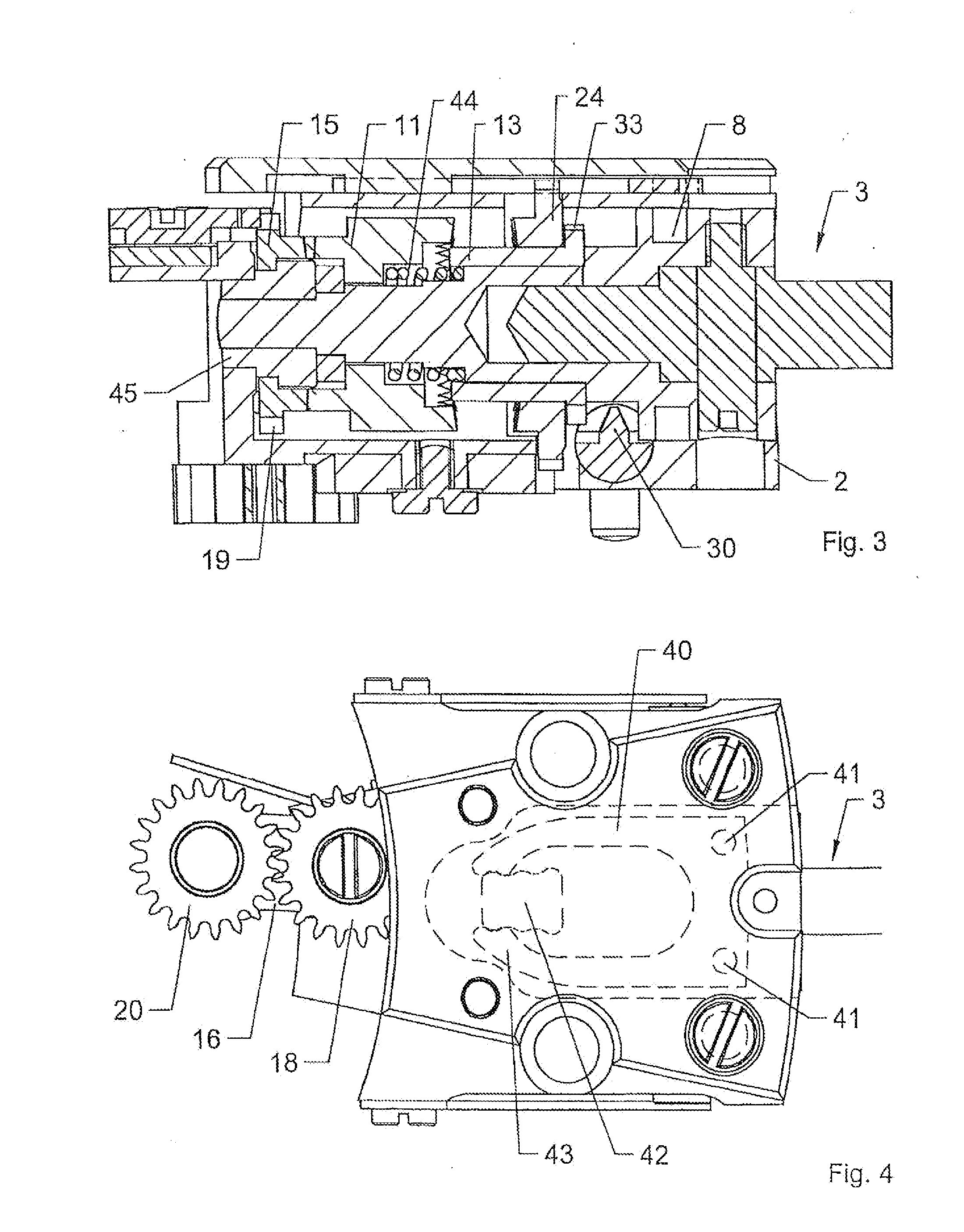
[0030]Described in reference to the figures is an embodiment of the mechanism and the timepiece module according to the invention, according to which the mechanism and the module comprise two control pinions and three actuating organs, i.e. a winding pinion, a setting wheel and a rack for actuating one other function, the control stem then being able to occupy three positions.

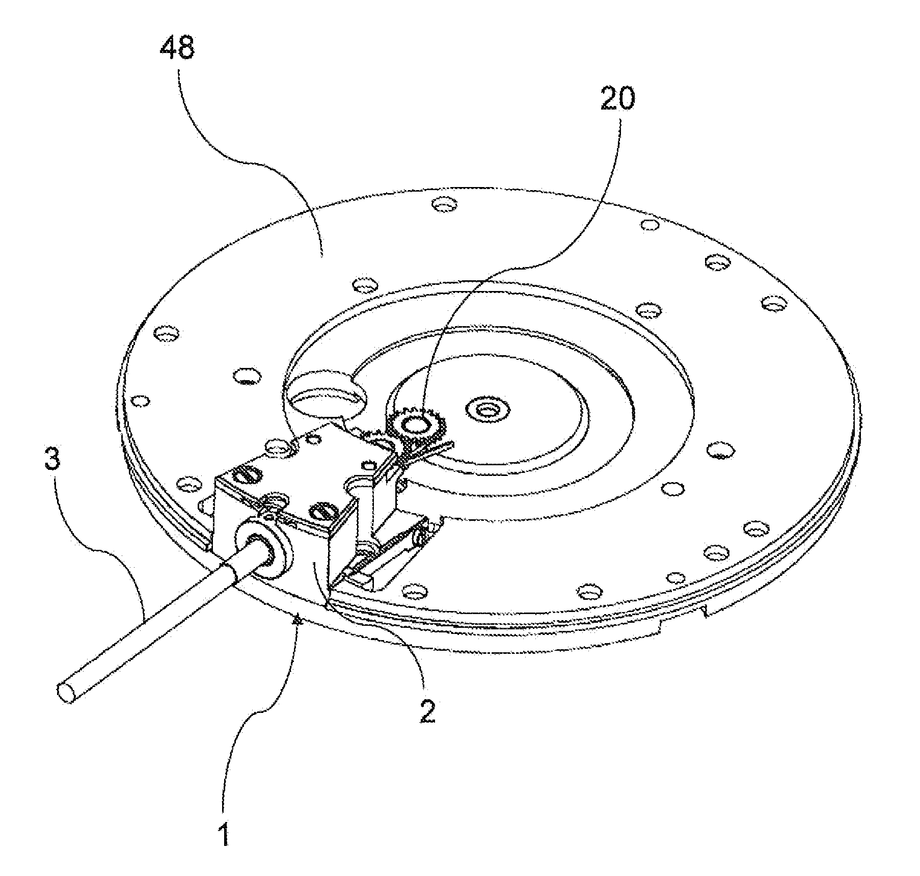
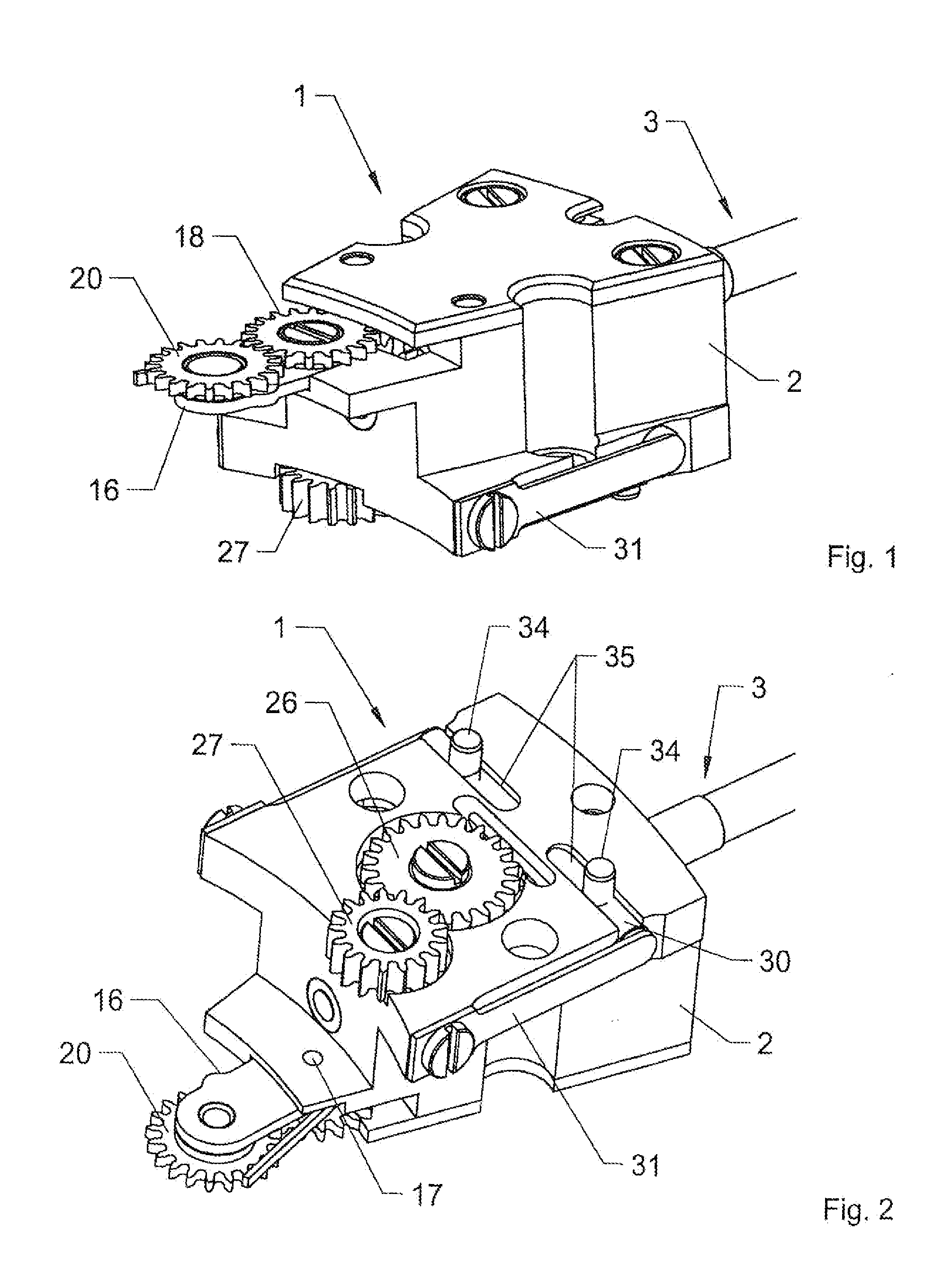
[0031]FIGS. 1 and 2 show a module 1 according to the invention comprising a case 2 and a mechanism for actuating an element of a timepiece movement.

[0032]In FIG. 5, the mechanism according to the invention comprises a control stem 3 mounted, inside the case 2, pivoting in the plane of the timepiece, and translationally movable between three axial positions. The control stem 3 comprises a first element 4 and a second element 5 essentially housed inside the case 2. The first element 4 is configured removably inside the second element 5 so as to be easy to disassemble and so that it is easy to remove the movement ...


PUM


Abstract

A mechanism and a timepiece module independent of the bottom plate of a movement, of a simple and compact design. The timepiece mechanism includes a control stem (3) mounted in a pivoting manner and movable between at least two axial positions, a control pinion (11; 13) mounted so as to rotate with the control stem (3), and at least one actuating member (15, 24; 30) configured to engage with the control pinion (11; 13) when the control stem is occupying one of the axial positions. The control pinion (11; 13) is also coupled translationally to the control stem (3) when the latter moves from one to the other of the two positions. The module includes a case (2) containing the mechanism.

Description

TECHNICAL FIELD [0001]The present invention concerns a timepiece mechanism comprising a control stem mounted in a pivoting manner and movable between at least two axial positions, a control pinion mounted so as to rotate with said control stem, and at least one actuating organ configured to engage with said control pinion when the control stem is occupying one of the axial positions. The invention also concerns a module comprising such a mechanism.BACKGROUND OF THE INVENTION[0002]This type of mechanism is for example a winding and setting mechanism that traditionally comprises a winding stem on which a castle wheel, rotating with the winding stem, can slide between a winding position and a setting position. In the winding position, the castle wheel engages with a first actuating organ formed by a winding pinion and in the setting position, the castle wheel engages with an appropriate intermediate wheel that constitutes a second actuating organ. The different parts are positioned on ...

Claims


Application Information

Patent Timeline
12 May 2011
Publication
US20110110199A1
IPC
G04B27/02
CPC
G04B27/04
Inventors
GIRARDIN, FREDERIC JOHNNY; ORNY, FRANCK-CHARLES-CYRIL