Device for injecting fuel to stationary internal combustion engines

a technology for injecting devices and internal combustion engines, which is applied in the direction of fuel injecting pumps, liquid fuel feeders, machines/engines, etc., can solve the problems of high pressure building up between the pump unit, design cannot completely eliminate cavitation defects, and the stable pressure level of the accumulator of the other fuel injectors is undisturbed

Inactive Publication Date: 2004-09-30
ROBERT BOSCH GMBH
View PDF12 Cites 28 Cited by
  • Summary
  • Abstract
  • Description
  • Claims
  • Application Information

AI Technical Summary

Benefits of technology

[0007] The modularity principle is also achieved in the design of the fuel injector used. The components used in these injectors include injection nozzles, intermediate plates with inlet and outlet throttles integrated into them, valve units, and injector bodies. By replacing the intermediate plate, for example, the pressure relief or pressure impingement of the control chamber of the injector can be influenced through the dimensioning of the throttle cross sections and can be adapted to an extremely wide variety of circumstances in which the injector is used. The injector body used in the modularly designed injector can be embodied in various lengths and can consequently be optimally adapted to the space available. The injector body includes an accumulator chamber whose accumulator volume is smaller, for example, than 80 times the maximally injected quantity of fuel. Highly pressurized fuel acts on this accumulator by means of an inlet throttle embodied in the head region of the fuel injector. Downstream of the accumulator integrated into the injector body, a flow limiter is provided, which limits the flow rate of fuel to the nozzle chamber. The inlet throttle to the accumulator in the head region of the injector is preferably designed to allow a multiple injection without pressure pulsations being produced in the high-pressure line segments that are connected to the head region of the fuel injector. This also leaves undisturbed the stable pressure level in the accumulators of the other fuel injectors. The inlet throttle can advantageously keep the pressure in the accumulator chamber integrated into the injector body at a pressure level that corresponds to the pressure level prevailing in a pressure accumulator integrated into one of the supply units.
[0008] Thanks to the small distance between the accumulator and the nozzle, the pressure pulsations in this accumulator and between the accumulator and the nozzle are considerably less intense than in conventional injection systems.
[0009] The accumulator chambers integrated into the injector bodies, their inlet throttles, and an accumulator chamber integrated into one of the supply units or disposed in the vicinity of them, render the respective injection events independent of the motor configuration of the engine, the length of the high-pressure line segments, and the number of cylinders in the engine. Due to the centralized disposition of the accumulator for damping pump pulsations, the injection system can be used in a large number of differently configured engines and consequently considerably reduces the large variety of components required. The accumulator chamber associated with the supply units and the pressure accumulators associated with the injectors are connected to one another by means of simple high-pressure line segments, which are modularly designed and can therefore be easily interchanged, which considerably simplifies the adaptation of the injection system to an extremely wide variety of internal combustion engine configurations and renders the quality of the injection events independent of the line length of the line segments connecting the accumulator chambers to one another.

Problems solved by technology

When the control valve is completely closed, however, both the first valve seat and the additional valve seat are closed, which interrupts the bypass connection.
This causes a high pressure to build up between the pump unit and the low-pressure region of the system, in comparison to the high-pressure region.
Because of the high flow speeds of the fuel between the injection phases--whether these be preinjection, main injection, or secondary injection phases--this design cannot completely eliminate cavitation defects.
This also leaves undisturbed the stable pressure level in the accumulators of the other fuel injectors.
Due to the centralized disposition of the accumulator for damping pump pulsations, the injection system can be used in a large number of differently configured engines and consequently considerably reduces the large variety of components required.

Method used


Image

  • Device for injecting fuel to stationary internal combustion engines
  • Device for injecting fuel to stationary internal combustion engines
  • Device for injecting fuel to stationary internal combustion engines

Examples


Embodiment Construction

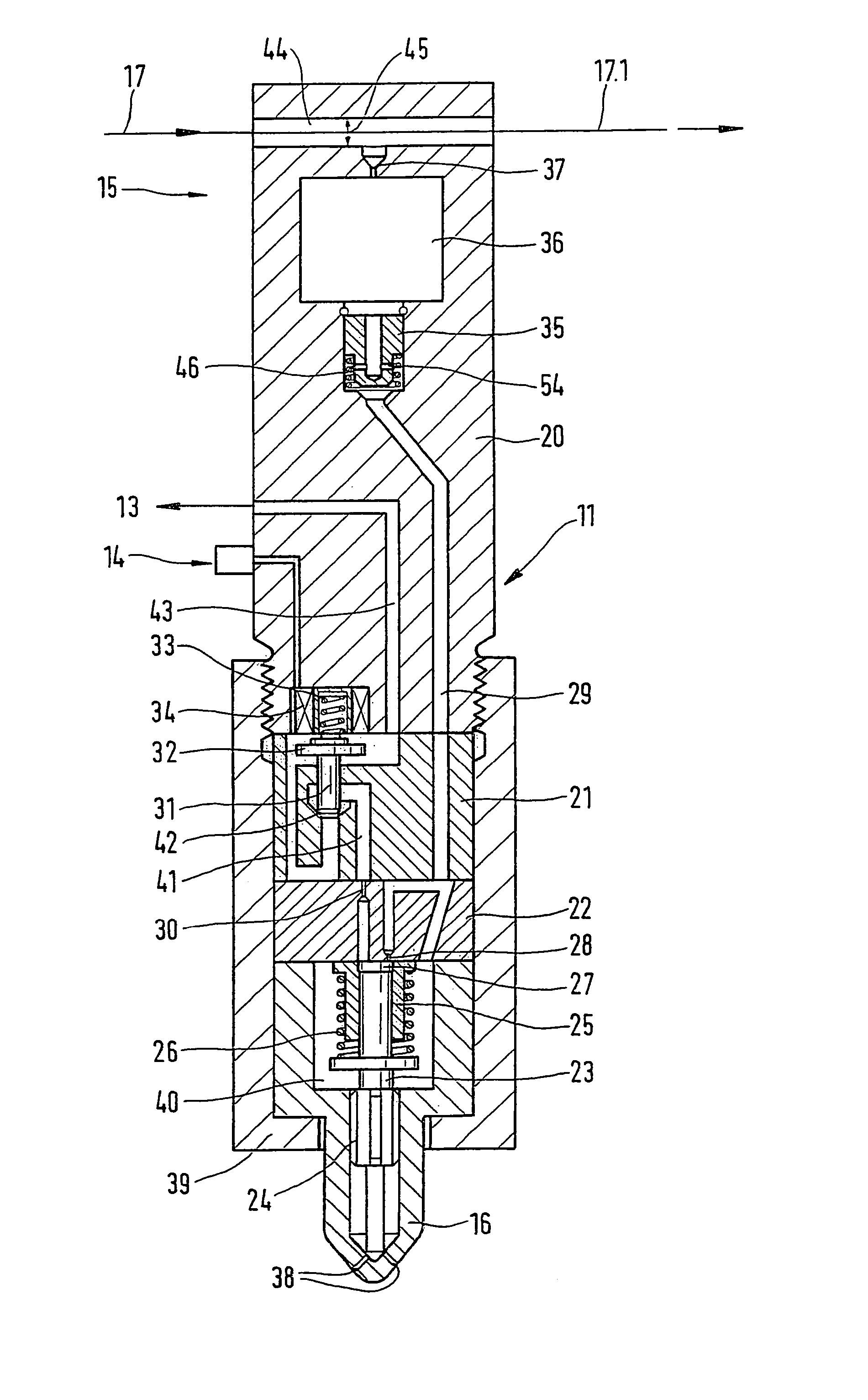
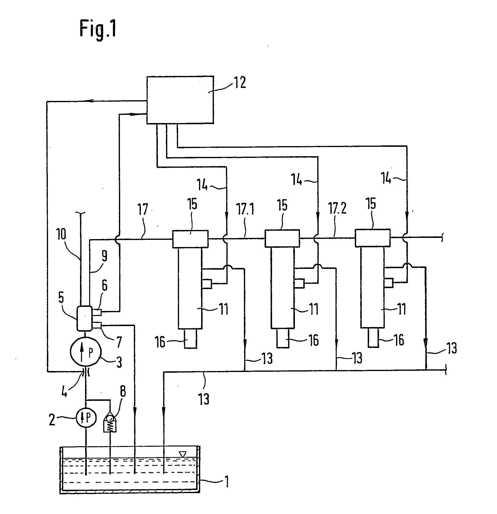
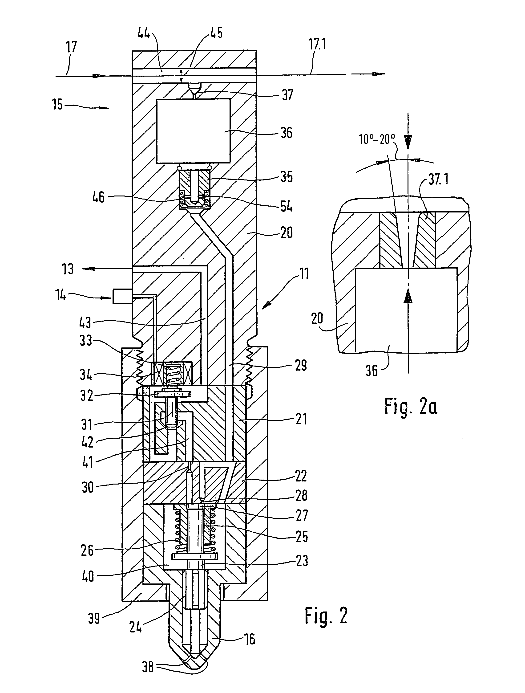
[0021] FIG. 1 shows the components of an injection system.

[0022] The injection system shown in FIG. 1, which is for supplying fuel to an internal combustion engine, includes a fuel reservoir 1. A fuel-supply pump 2 delivers fuel from the fuel reservoir 1. On the pressure side, the fuel-supply pump 2 has a high-pressure pump unit 3 connected downstream of it, which is preceded by a throttle restriction 4. The throttle restriction 4 is designed to be variable and can be triggered by means of a control unit 12. The fuel-supply pump 2 has a pressure control valve 8 connected downstream of it, which controls the supply pressure to the high-pressure pump unit 3 and is connected to the fuel reservoir 1.

[0023] The high-pressure pump unit 3 includes an integrated pressure accumulator 5. A pressure relief valve 7 whose outlet feeds into the fuel reservoir 1 protects the pressure accumulator 5. The integrated pressure accumulator 5 also has a pressure sensor 6, which is connected to the contro...


PUM


Abstract

The invention relates to a fuel injection system for use in internal combustion engines. The injection system has having delivery units (2, 3) for delivering fuel from a fuel reservoir (1) in order to supply at least one high-pressure line (9, 10) to the cylinders of the engine. The at least one high-pressure line (9, 10) supplies a number of fuel injectors (11), which each include an injector nozzle (16) that supplies fuel to a combustion chamber of the engine. The at least one high-pressure line (9, 10) and includes line segments (17, 17.1, 17.2) that connect the individual fuel injectors (11) to one another. The injector bodies (20) of the fuel injectors (11) each have an accumulator chamber (36, 36.1) integrated into them.

Description

[0001] Internal combustion engines that are used as vehicle motors, stationary motors (generator motors), or for propelling ships as a rule have between 2 and 20 cylinders. In these engines, the bore diameter of the respective cylinders lies within a broad spectrum, sometimes reaching 500 mm in large diesel engines. Depending on the number of cylinders, individually customized fuel injection systems are used, which must be individually tailored to the number of cylinders.[0002] 1. Prior Art[0003] DE 198 37 332 A1 relates to a control unit for controlling the buildup of pressure in a pump unit. The control unit has a control valve with a valve-actuating unit connected to it. The control valve is embodied as an I-valve that opens inward in the flow direction and has a valve body that is supported so that it can slide axially in housing of the control unit and when the control valve is closed, rests against a valve seat of the control valve from the inside. A throttle device is provide...

Claims


Application Information

Patent Timeline
Patent Type & Authority Applications(United States)
IPC IPC(8): F02B3/06F02M47/00F02M47/02F02M51/06F02M55/02F02M55/04F02M61/10F02M63/00F02M63/02
CPCF02B3/06F02F2007/0097F02M47/027F02M2200/40F02M55/04F02M63/0215F02M63/0225F02M55/025
Inventor HLOUSEK, JAROSLAW
Owner ROBERT BOSCH GMBH
Why Eureka
Try Eureka