Base anchoring structure

Inactive Publication Date: 2011-05-19
MITAKA KOHKI
View PDF15 Cites 10 Cited by
  • Summary
  • Abstract
  • Description
  • Claims
  • Application Information

AI Technical Summary

Benefits of technology

[0005]According to the related art, the plurality of leg is lowered in an integrated manner to a floor, and therefore, the legs will be imbalanced on the floor if the floor has irregu

Problems solved by technology

According to the related art, the plurality of leg is lowered in an integrated manner to a fl

Method used


Image

  • Base anchoring structure
  • Base anchoring structure
  • Base anchoring structure

Examples


Embodiment Construction

[0016]An embodiment of invention will be explained with reference to the drawings.

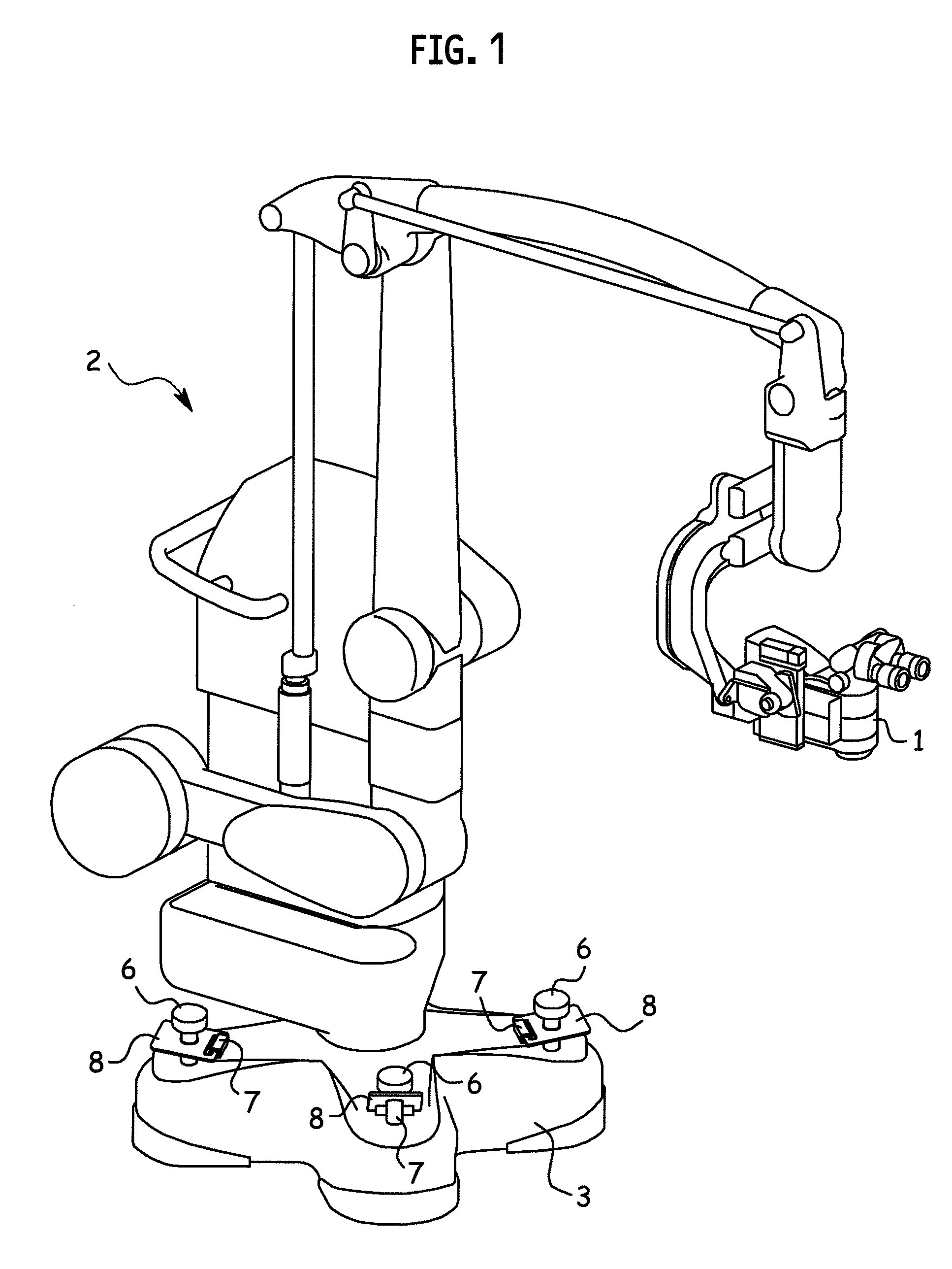
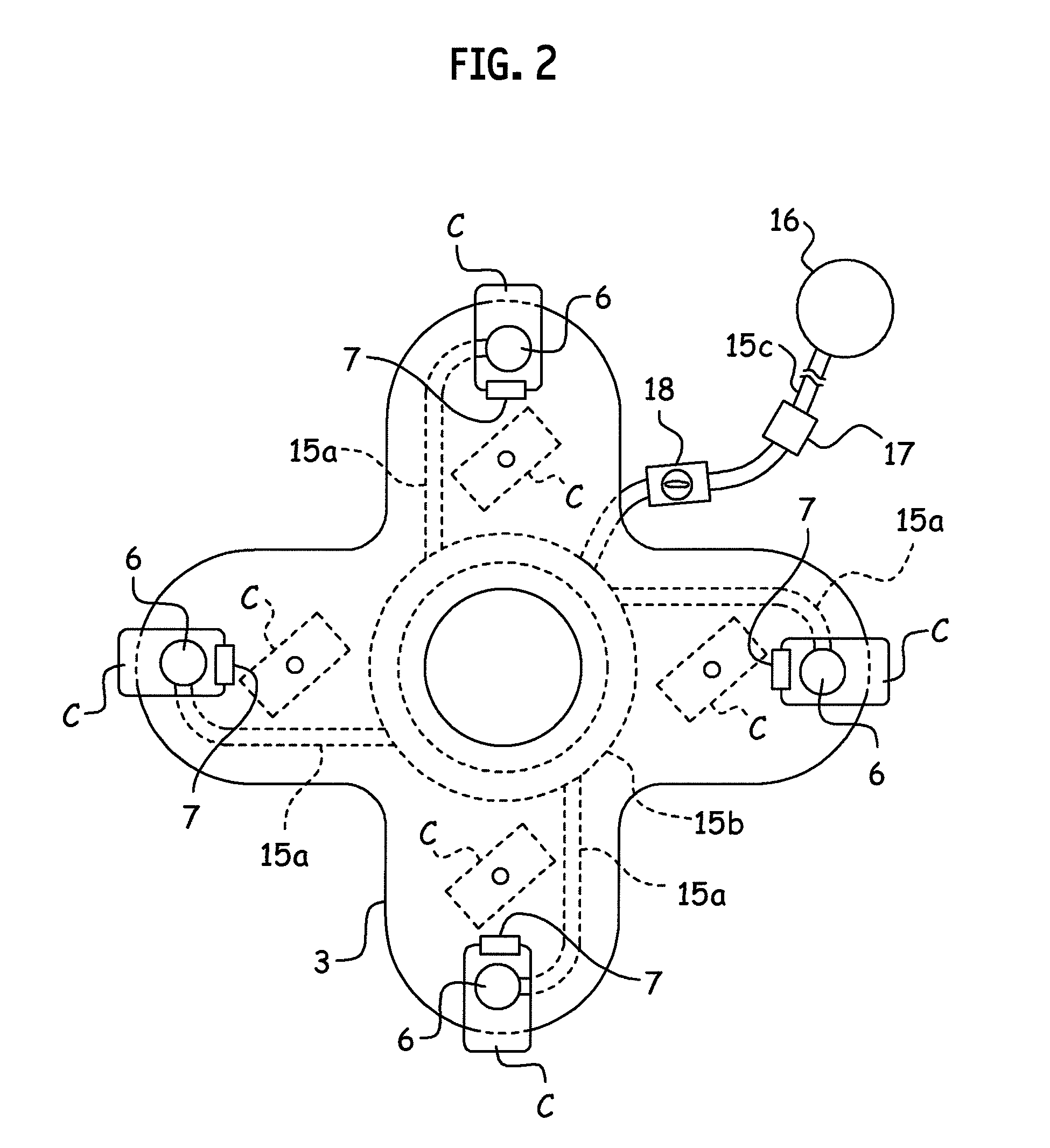
[0017]FIG. 1 illustrates a medical stand apparatus 2 supporting a surgical microscope 1. The stand apparatus 2 corresponds to the “apparatus body” stipulated in the claims. At a lower part of the stand apparatus 2, there is a base 3 provided with a base anchoring structure according to an embodiment. The base 3 substantially has a cross shape and is hollow with the bottom thereof opened.

[0018]The base 3 has four casters C at four locations. The casters C correspond to the “moving units” stipulated in the claims. The casters C roll on a floor F, to move and turn the stand apparatus 2 on the floor F.

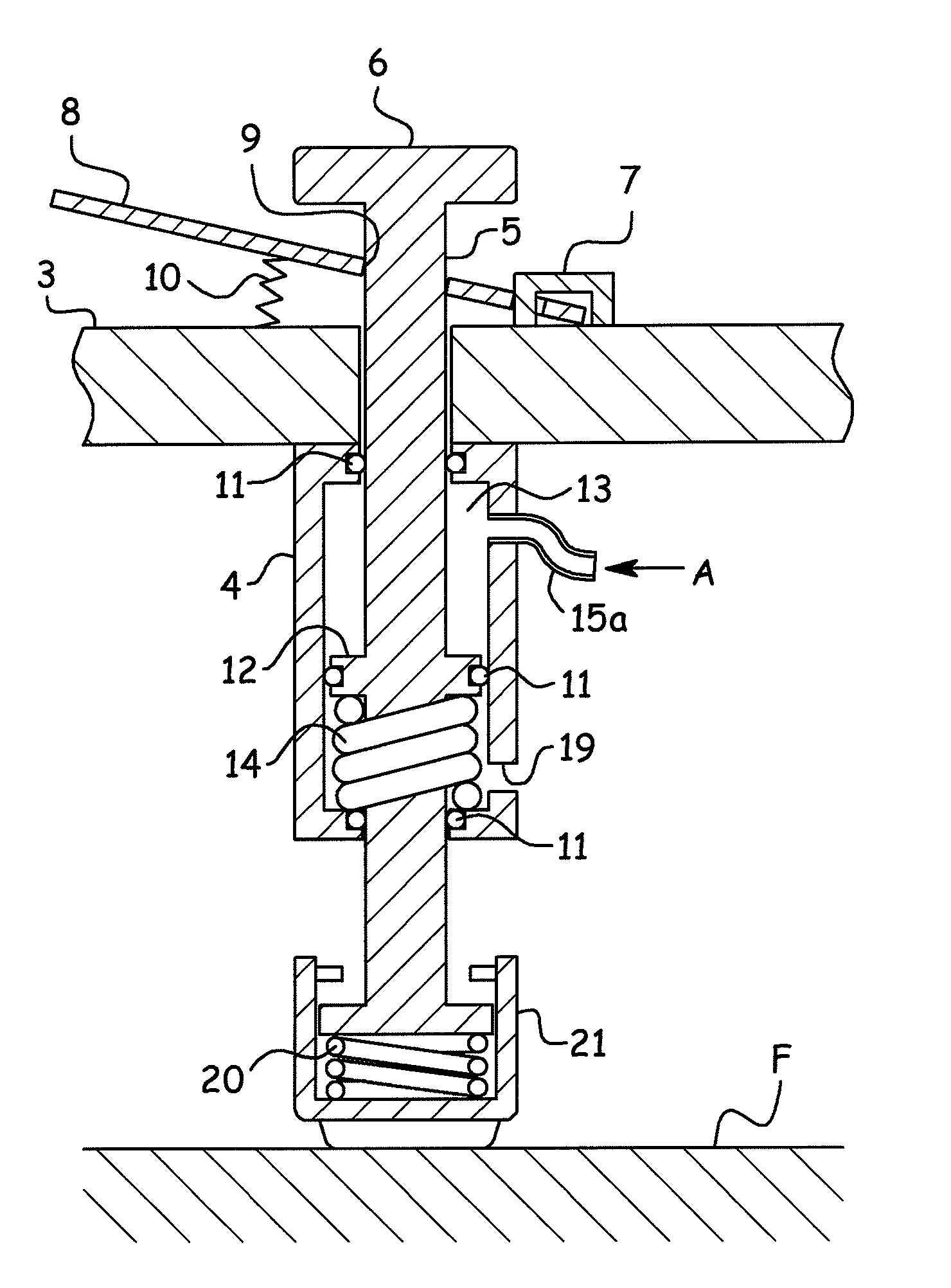
[0019]Each of four corners of the base 3 is provided with a linear actuator 4. The linear actuators 4 are parts of the base anchoring structure according to the present embodiment. Each actuator 4 has a vertical cylinder that accommodates a piston 5. The piston 5 vertically passes through the cylinder. An upp...


PUM


Abstract

A base anchoring structure fixes a base 3 of an apparatus body 2 to a floor F in position. The base is at a lower part of the apparatus body and has casters C to move the apparatus body along the floor. The base anchoring structure includes linear actuators 4 fixed to the base, to downwardly bias, with a uniform pressure provided by air A supplied to the linear actuators, their respective pistons 5 until lower ends of the pistons reach the floor and stopper units (7, 8, 10) to engage with the downwardly pushed pistons and stably maintain the downwardly pushed state of the pistons. The engagement of the stopper units with the pistons stably maintains the anchored state of the base. The plurality of actuator is easily operated only by supplying air thereto.

Description

BACKGROUND OF THE INVENTION[0001]1. Field of the Invention[0002]The present invention relates to a base anchoring structure for fixing a base of an apparatus body to a floor in position.[0003]2. Description of the Related Art[0004]A base is arranged at a lower part of an apparatus body, to support the apparatus body in an upright position and move / anchor the apparatus body with respect to a floor. To move and anchor the apparatus body, the base has a moving device such as a caster as well as an anchoring device such as a stopper. The base also has a lifting device that selectively lowers and lifts the moving and anchoring devices, to establish a movable or anchored state of the apparatus body. An example of the anchoring device is disclosed in Japanese Unexamined Patent Application Publication No. H10-16505. This related art lowers a plurality of legs in an integrated fashion to a floor.SUMMARY OF THE INVENTION[0005]According to the related art, the plurality of leg is lowered in an...

Claims


Application Information

Patent Timeline
IPC IPC(8): F16F15/023A47B91/08F16F1/00
CPCB23Q1/0054G02B21/0012G02B7/001F16M7/00
Inventor NAKATA, YUSUKEDOI, MASAOHASHIMOTO, TATSUYA
Owner MITAKA KOHKI
Why Eureka
Try Eureka