Turbogenerator with cooling system

Active Publication Date: 2011-05-19
GENERAL ELECTRIC CO
View PDF17 Cites 21 Cited by
  • Summary
  • Abstract
  • Description
  • Claims
  • Application Information

AI Technical Summary

Problems solved by technology

Turbogenerators, such as independent APU power sources to meet the power requirement, can provide enough power but are slow (on the order of 4 sec).
These systems typically require large RAM air heat exchangers for thermal management of the large heat loads generated by the DEW.

Method used


Image

  • Turbogenerator with cooling system
  • Turbogenerator with cooling system

Examples


Embodiment Construction

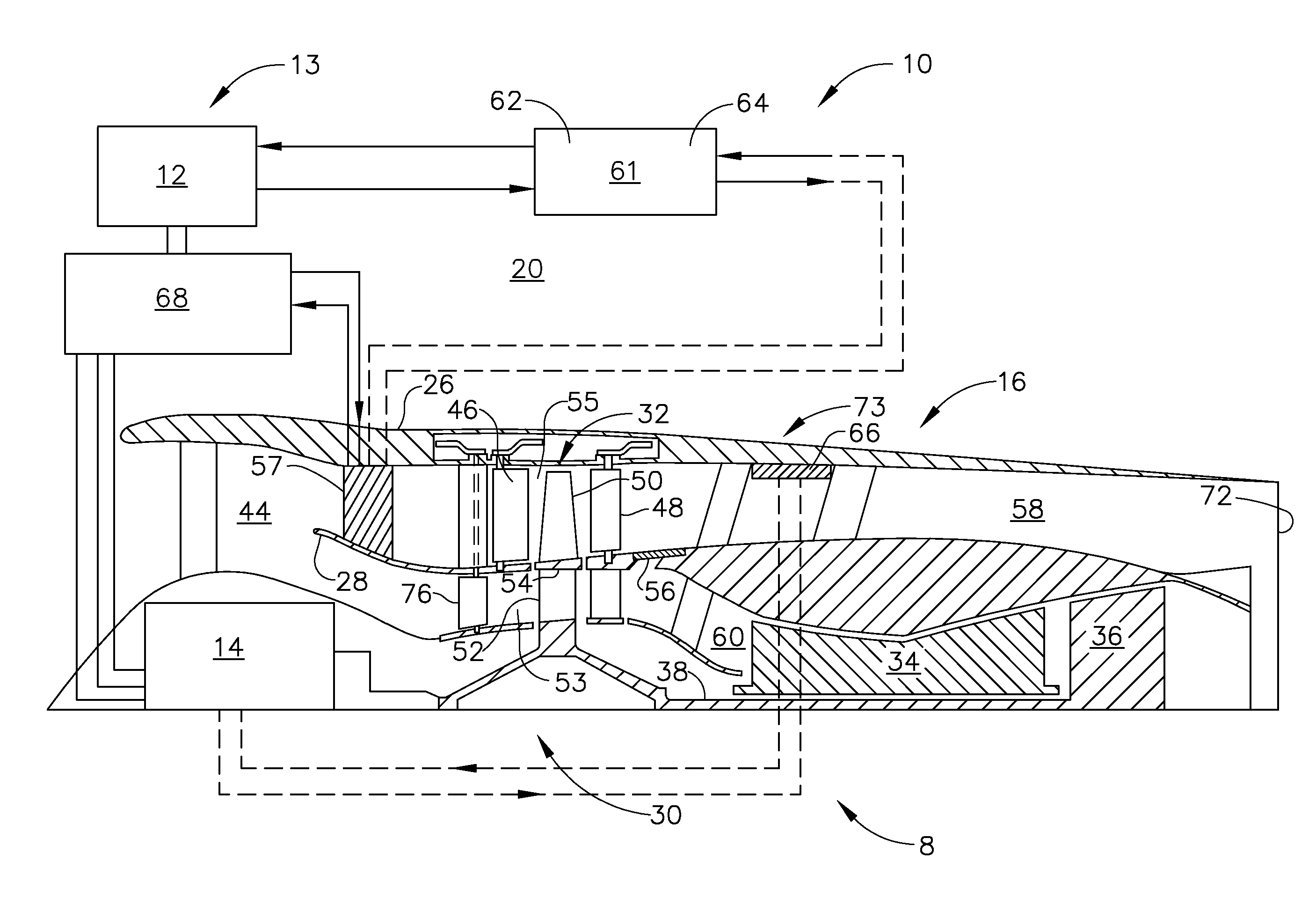
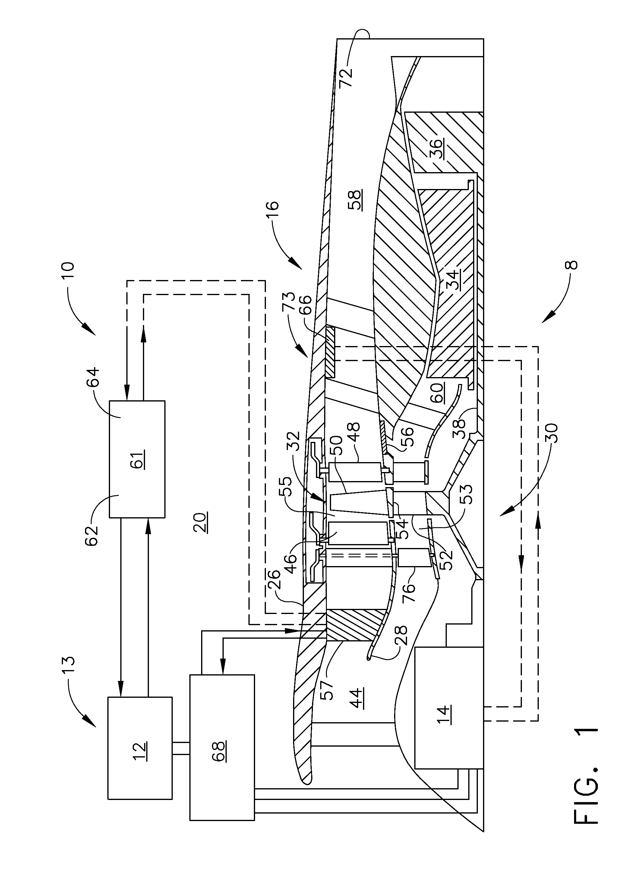
[0013]FIG. 1 illustrates an exemplary high energy system 8 in the form of a directed energy weapon system 10 including a directed energy weapon 12 (DEW) powered by an electrical generator 14 in a turbogenerator 16. The turbogenerator 16 includes a gas turbine engine 30 operable to power the generator 14 and a cooling system 20 for cooling the directed energy weapon system 10. The directed energy weapon system 10 further includes conditioning power electronics 68 operably disposed between the generator 14 and the directed energy weapon 12 for conditioning the electricity produced by the electrical generator 14 for operating and firing the directed energy weapon 12. The gas turbine engine 30 is operable to switch between exclusively powering the generator 14 and exclusively powering the cooling system 20 or powering both simultaneously.

[0014]A fan 32 upstream of a core engine 34, also referred to as a gas generator, is drivenly connected to a low pressure turbine 36 that supplies powe...


PUM


Abstract

A turbogenerator having a gas turbine engine powering generator and a cooling system and an annular heat exchanger powered by a fan disposed across an outer fan duct of the engine. Fan variable inlet and outlet guide vanes may be used to vary power between the fan and the generator which are drivenly connected to a low pressure turbine. Inner and outer portions separated by a rotating shroud of the fan are disposed in annular inner and outer fan ducts respectively. A directed energy weapon may be powered by the generator and cooled by the cooling system. A refrigeration apparatus may be operably disposed between the annular heat exchanger and the directed energy weapon for cooling the directed energy weapon and conditioning power electronics for the weapon. The refrigeration apparatus may include a vapor cycle cooling system and a cold storage containing a phase change material.

Description

BACKGROUND OF THE INVENTION[0001]1. Field of the Invention[0002]The present invention relates to gas turbine engine powered generators or turbogenerators and cooling and thermal management systems.[0003]2. Description of Related Art[0004]Directed energy weapons (DEW) require megawatts (in a range of between 1-5 megawatts or more) of fast (e.g. less than 0.1 sec) on / off pulsing power. They also require megawatts of heat removal that can be provided by gas turbines driving electrical generators, also referred to as turbogenerators. Turbogenerators, such as independent APU power sources to meet the power requirement, can provide enough power but are slow (on the order of 4 sec). Batteries and complicated power electronics are often used to meet the transient power requirements. These systems typically require large RAM air heat exchangers for thermal management of the large heat loads generated by the DEW.[0005]Directed energy weapons are representative of very high power devices in hi...

Claims


Application Information

Patent Timeline
Patent Type & Authority Applications(United States)
IPC IPC(8): H02K7/18F02C7/12
CPCF01D15/10F05D2220/76H02K7/1823F02K3/115
Inventor SHAFER, DOUGLAS GEORGERETTIG, MARK GERARDVANDERMOLEN, ROBERT JOHN
Owner GENERAL ELECTRIC CO
Why Eureka
Try Eureka