Method of driving electro-optical device, electro-optical device, and electronic apparatus

a technology of electrooptical devices and electronic devices, applied in the direction of instruments, computing, electric digital data processing, etc., can solve the problems of ineffective practical solution, increased risk of direct current component burn-in of display screens, and generation of direct-current components

Inactive Publication Date: 2011-05-19
SEIKO EPSON CORP
View PDF6 Cites 8 Cited by
  • Summary
  • Abstract
  • Description
  • Claims
  • Application Information

AI Technical Summary

Benefits of technology

[0009]An advantage of some aspects of the invention is to provide a method of driving an electro-optical device, the electro-optical device, and an electronic apparatus that can provide a solution to at least a part of the above problem without any limitation thereto.

Problems solved by technology

Consequently, without any measure taken against such a phenomenon, a direct-current component would be generated as a predictable problem.
The generation a direct-current component increases the risk of the burn-in of a display screen.
There are various reasons why the above solution might not be so effective practically.
However, it is practically difficult to meet the preconditions.
This is partially because the changing of the counter electrode potential would have a significant impact on other settings and partially because it is uncertain whether the effects of pushdown could be really offset or not due to the reason described above even if the counter electrode potential were changed.
To sum up the matter, the solution of related art has a disadvantage in that its flexibility as a measure for effectively avoiding the adverse effects of pushdown is rather limited.

Method used


Image

  • Method of driving electro-optical device, electro-optical device, and electronic apparatus
  • Method of driving electro-optical device, electro-optical device, and electronic apparatus
  • Method of driving electro-optical device, electro-optical device, and electronic apparatus

Examples


Embodiment Construction

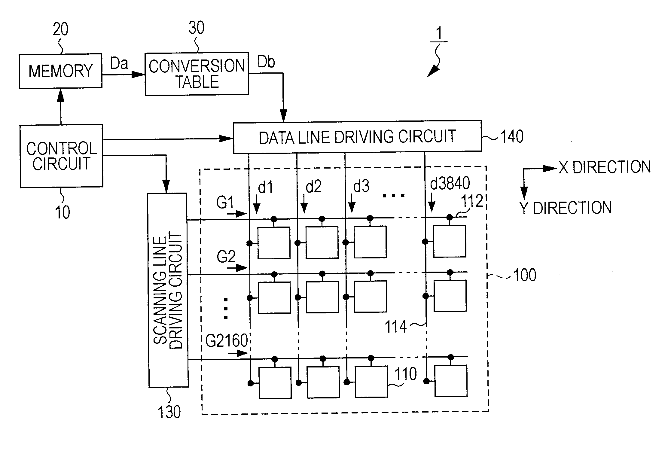
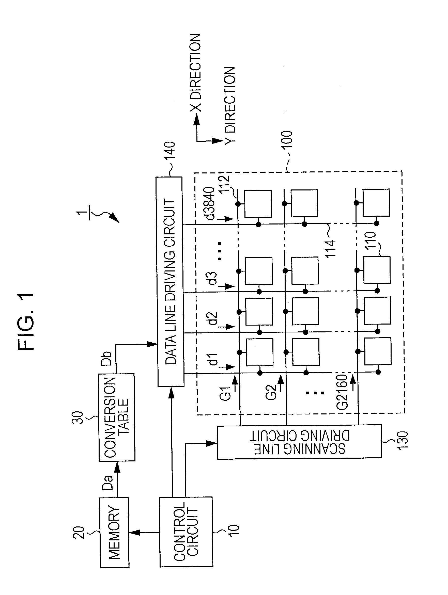
[0036]With reference to FIGS. 1 and 2, an exemplary embodiment of the invention will now be explained. FIG. 1 is a block diagram that schematically illustrates an example of the overall configuration of an electro-optical device 1 according to an exemplary embodiment of the invention. As illustrated in FIG. 1, the electro-optical device 1 includes a control circuit 10, a memory 20, a conversion table 30, a display area 100, a scanning line driving circuit 130, and a data line driving circuit 140 as its main components. The control circuit 10 controls these components as will be described later.

[0037]A plurality of pixels is arranged in a matrix pattern in the display area 100. Specifically, a plurality of scanning lines (writing scan lines) 112 and a plurality of data lines 114 are formed in the display area 100. Each of the scanning lines 112 extends in the X direction, which is the horizontal direction in FIG. 1. Each of the data lines 114 extends in the Y direction, which is the ...


PUM


Abstract

An electro-optical device includes: a data line driver applying the signal potential in such a manner that a writing polarity is reversed more than once in the field time period, and the writing polarity of each of sub field time periods making up a certain field time period is the opposite of the writing polarity of the corresponding one of sub field time periods making up the next field time period; a scanning line driver applying the scanning signal in such a manner that a total length of the sub field time periods in which writing in one polarity is performed in each cycle of two consecutive fields one of which is an odd field and the other of which is an even field is different from a total length of the sub field time periods in which writing in the other polarity is performed in the each cycle of two consecutive fields.

Description

BACKGROUND[0001]1. Technical Field[0002]The present invention relates to a method of driving an electro-optical device that uses an electro-optical material such as liquid crystal, the electro-optical device, and an electronic apparatus.[0003]2. Related Art[0004]Liquid crystal is known as an example of electro-optical materials that have optical characteristics that change depending on electric energy. The transmission factor of liquid crystal changes as a voltage applied changes. The change in the transmission factor occurs due to a change in the orientation state of liquid crystal molecules depending on the voltage applied. As the characteristics of liquid crystal, its orientation state is less liable to return to an original state when a direct-current voltage is applied for a long period of time. In consideration of the above characteristics, an alternating-current driving method is generally used in a liquid crystal display device, which uses liquid crystal as its display mediu...

Claims


Application Information

Patent Timeline
Patent Type & Authority Applications(United States)
IPC IPC(8): G09G5/00G09G3/36
CPCG09G3/204G09G3/3614G09G2320/0276G09G2320/0219G09G3/3648
Inventor HARA, HIROYUKI
Owner SEIKO EPSON CORP
Why Eureka
Try Eureka