Stent having an expandable web structure

a web structure and stent technology, applied in the field of stents, can solve the problems of decreasing the length of the stent, or foreshortening, along the longitudinal axis, and the non-uniformity of the stent in the deployed configuration, and achieve the effect of maintaining the patency of the sten

Inactive Publication Date: 2011-05-26
ABBOTT INT ENTERPRISES LTD
View PDF20 Cites 2 Cited by
  • Summary
  • Abstract
  • Description
  • Claims
  • Application Information

AI Technical Summary

Benefits of technology

[0009]It is another object of the present invention to provide a stent that experiences reduced foreshortening, thereby reducing non-uniformity resulting from contraction and subsequent expansion of the stent.
[0010]It is a further object of the present invention to provide a stent that retains a homogenous cross-section and stress distribution after deployment.
[0013]Preferably, each X-shaped transition section is produced by contacting the upward end of a bend interconnecting two concave struts with the neighboring downward end of a bend interconnecting two concave struts. This arrangement causes the X-shaped transition section to be disposed at an angle relation to the longitudinal axis of the stent, thereby reducing the empty spaces between the web patterns. Also preferably, the X-shaped transition sections connect one out of every three couples of adjacent bends, and the transition sections extending from one end of a web pattern are staggered in relation to the transition sections extending from the opposite end of the same web pattern.
[0018]As will be apparent to one skilled in the art, the position, distribution density, and thickness of adjoining struts and X-shaped transition sections may be varied to provide stents with characteristics tailored to specific applications, such as implantations in coronary arteries or in peripheral arteries, for example, renal arteries. Position, distribution density, and thickness also may be varied to provide varying flexibility and radial stiffness properties along the length of an individual stent.
[0019]A stent according to the present invention minimizes stent non-uniformity during contraction and expansion of the stent, because variations in stent length and properties are reduced by the X-shaped transition sections. This beneficial effect is caused by having transition sections between adjacent web patterns that are positioned near the mid-points between web patterns.
[0020]Stents according to the present invention are longitudinally flexible in the delivery configuration, so to increase a clinician's ability to guide the stent to a target site within a patient's vessel, but are radially stiff in the deployed configuration, so to withstand the compressive forces applied by a vessel wall and maintain vessel patency. The web structure described hereinabove provides such a desirable combination of flexibility in the delivery configuration and radial stiffness in the deployed configuration.

Problems solved by technology

A common drawback of such stents is that the stent decreases in length, or foreshortens, along its longitudinal axis as it expands.
Such foreshortening is undesirable because, in the deployed configuration, the stent may not span the entire area inside a vessel or orifice that requires expansion and / or support.
In addition, foreshortening may result in non-uniformity of the stent in the deployed configuration.

Method used


Image

  • Stent having an expandable web structure
  • Stent having an expandable web structure
  • Stent having an expandable web structure

Examples


first embodiment

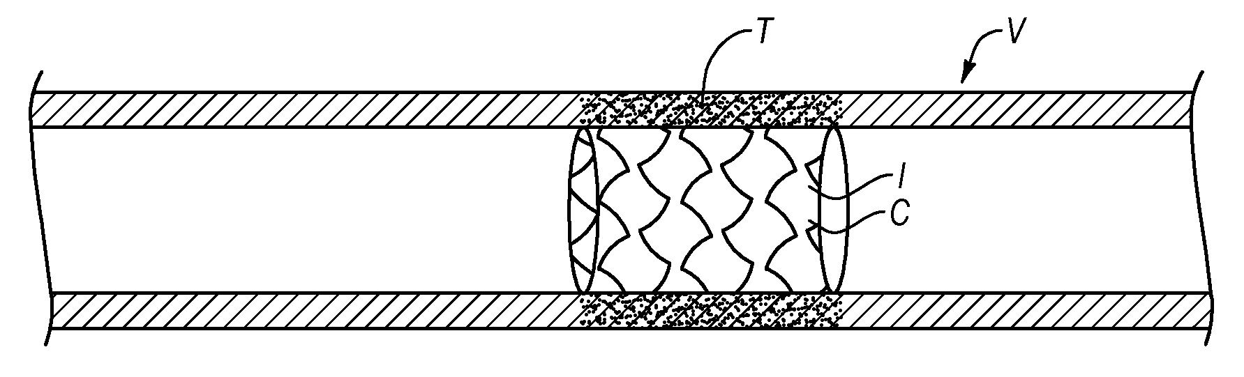
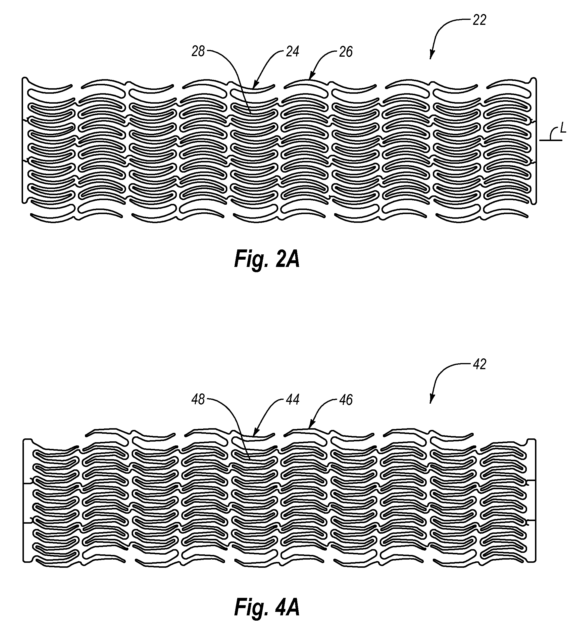
[0030]FIGS. 2A-2C represent detail views of the present invention. Wall 18 is composed of web structure 22, which, for illustrative purposes, is shown flattened into a plane. More particularly, FIG. 2A illustrates the pattern and orientation of web structure 22 in relation to the longitudinal axis L of stent 10.

[0031]Web structure 22 is formed by a plurality of neighboring web patterns 24 and 26, which extend circumferentially around tubular body 12 and which are arranged side by side. Thus, web patterns 24 and 26 are arranged longitudinally in the sequence 24, 26, 24, 26, etc.

[0032]As shown in FIGS. 2A-2B, web patterns 24 and 26 each comprise a plurality of arcuate struts 28, arranged with alternating concavity relative to the circumferential of the stent. Each of arcuate struts 28 is connected sequentially to the adjoining strut inside the same web pattern by bend 30, and arcuate struts 28 are disposed in a nested arrangement to form a stack of substantially parallel curvilinear s...

second embodiment

[0043]Turning now to FIGS. 4A-4C, there is shown the invention. Web structure 42 is formed by a plurality of web patterns 44 and 46, which are disposed in alternating positions, in the manner shown for web patterns 24 and 26 of the embodiment of FIG. 2A. Each of web patterns 44 and 46 is formed by a plurality of struts 48, which have alternating concavities and which are parallel and nested into each other, also in the same fashion as struts 28 in FIG. 2A. As shown in FIG. 4B, each of struts 48 comprises a series of straight and curved segments, or by a series of straight segments 50 (three in the embodiment illustrated in FIG. 4B) disposed next to each other to form obtuse angles therebetween.

[0044]Adjacent struts 50 within a web pattern are sequentially connected one to the other by bend 52, and neighboring web patterns are interconnected by means of a plurality of X-shaped transition sections 54, that couple pairs of adjacent bends 52, positioned on neighboring web patterns 44 an...


PUM


Abstract

A stent comprises a tubular flexible body composed of a web structure that is expandable from a contracted delivery configuration to a deployed configuration and that comprises neighboring web patterns of alternating concavities extending circumferentially and adjoined by X-shaped transition sections. The web pattern may comprise either arcuate struts interconnected by bends, or a plurality of substantially straight sections with the transition sections formed by the junctions between pairs of adjacent bends of opposite curvatures.

Description

RELATED APPLICATIONS[0001]The present application is a continuation in part application of U.S. patent application Ser. No. 10 / 743,857, filed on Dec. 22, 2003, which is a continuation application of U.S. patent application Ser. No. 09 / 742,144, filed Dec. 19, 2000, now U.S. Pat. No. 6,682,554, which is a continuation-in-part application of U.S. patent application Ser. No. 09 / 582,318, filed Jun. 23, 2000, now U.S. Pat. No. 6,602,285, which claims the benefit of the filing date of International Application PCT / EP99 / 06456, filed Sep. 2, 1999, which claims priority from German application 19840645.2, filed Sep. 5, 1998, which are incorporated herein by reference.FIELD OF THE INVENTION[0002]The present invention relates to stents. More particularly, the present invention relates to stents having a web structure that minimizes stent non-uniformity during crimping and subsequent expansion of the stent.BACKGROUND OF THE INVENTION[0003]Stents are tubular structures that are implanted inside t...

Claims


Application Information

Patent Timeline
Patent Type & Authority Applications(United States)
IPC IPC(8): A61F2/82A61F2/90
CPCA61F2/91A61F2/915A61F2002/91508A61F2230/0054A61F2002/91558A61F2210/0076A61F2002/91533
Inventor SCHNEIDER, RALPH
Owner ABBOTT INT ENTERPRISES LTD
Why Eureka
Try Eureka