Postage Label Dispensing System Having A Peeler Plow For Dispensing Application Ready and/or Lined Postage Labels

a postage label and peeler plow technology, applied in the direction of mechanical control devices, instruments, process and machine control, etc., can solve the problems of laborious/costly operation, the automated system for separating the adhesive-backed label face from the liner is complex, and the operator does not have the option of applying the label

Active Publication Date: 2011-06-02
PITNEY BOWES INC
View PDF5 Cites 7 Cited by
  • Summary
  • Abstract
  • Description
  • Claims
  • Application Information

AI Technical Summary

Problems solved by technology

However, the operator is tasked with removing the adhesive backed label from the liner at the time of application which can be a laborious / costly operation.
With respect to the former, it will be appreciated that the automated system for separating the adhesive-backed label face from the liner can be complex, and does not provide the operator with the option of applying the label at a remote location.
With respect to the latter, the option to print a postage indicia / franking label is often selected when the surface contour of the mailpiece envelope is irregular and printing directly on the face may result in a distorted image.
In addition to the various shortcomings associated with conventional label fabrication / dispensing systems, mailing machines introduce the added complexity of printing currency on the labels which are fabricated.

Method used


Image

  • Postage Label Dispensing System Having A Peeler Plow For Dispensing Application Ready and/or Lined Postage Labels
  • Postage Label Dispensing System Having A Peeler Plow For Dispensing Application Ready and/or Lined Postage Labels
  • Postage Label Dispensing System Having A Peeler Plow For Dispensing Application Ready and/or Lined Postage Labels

Examples


Embodiment Construction

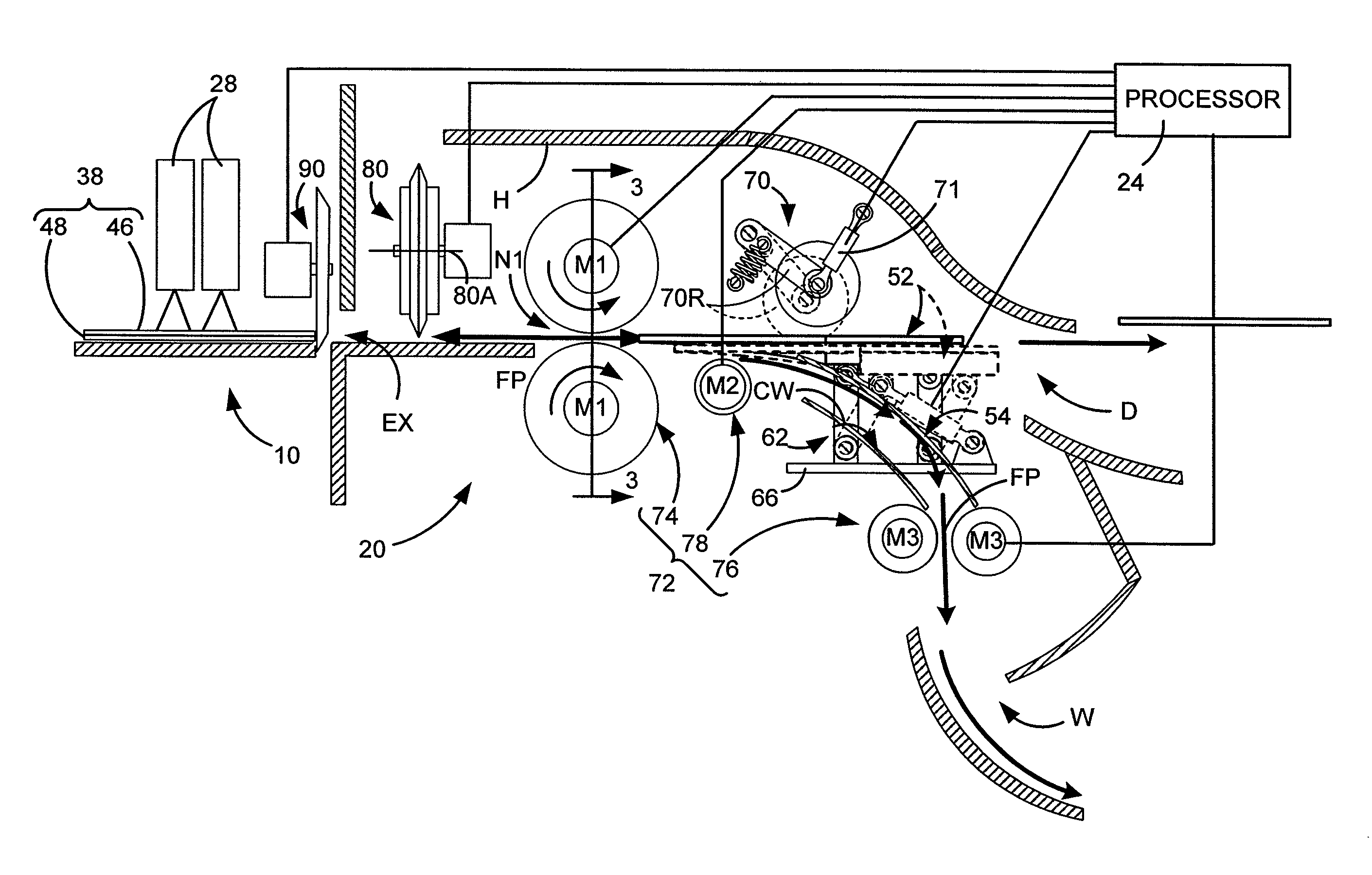
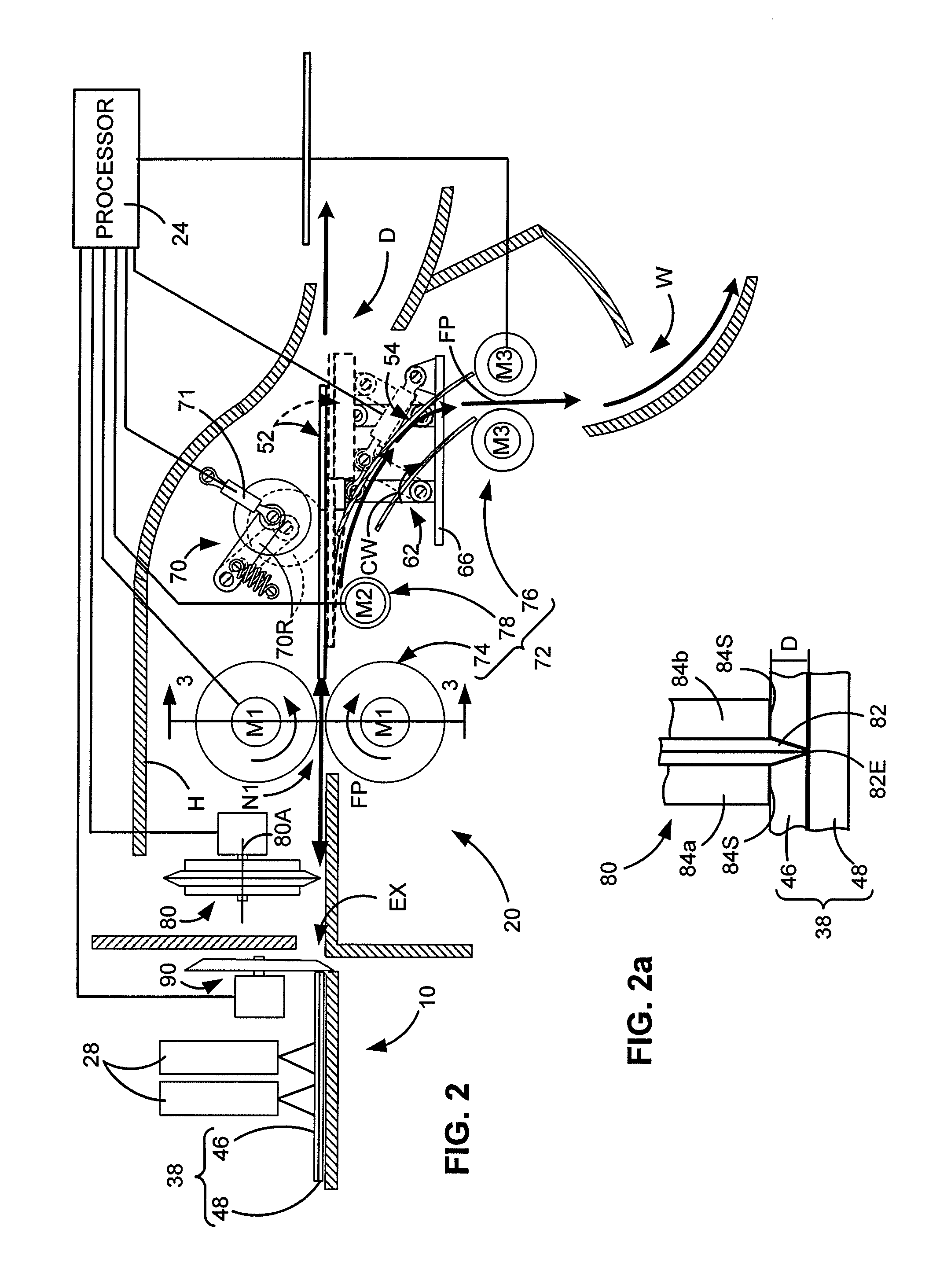
[0024]A system for dispensing and / or fabricating adhesive-backed labels is described herein. The invention is described in the context of a system for dispensing printed labels, a removable module for dispensing printed labels, and a system for fabricating and dispensing postage labels. The inventive teachings are also described in the context of a mailing machine for printing postage indicia / franking labels, although, it should be appreciated that any label producing and / or dispensing apparatus may be employed. A mailing machine merely provides an illustrative example of one embodiment of the invention, and should not be considered limiting when interpreting the meaning and / or scope of the appended claims.

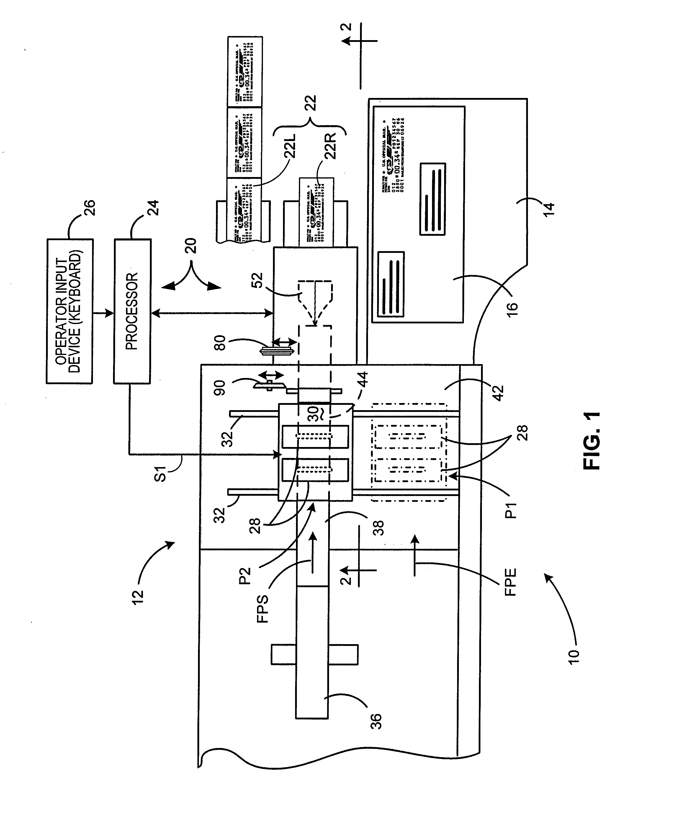
[0025]FIG. 1 depicts a schematic, broken-away top view of a mailing machine 10 according to the teachings of the present invention. In particular, the views illustrate a print station 12 in combination with a forward stacking tray 14 for receiving finished mailpieces 16, and a sys...


PUM

PropertyMeasurementUnit
sizeaaaaaaaaaa
sizeaaaaaaaaaa
areaaaaaaaaaaa

Abstract

A postage label dispensing system for dispensing adhesive-backed labels includes a conveyance system for displacing a supply of label material along a feed path wherein the label material includes a face material having an adhesive backing and a liner material detachably bonded to the adhesive backing. The adhesive backing defines a pair of longitudinal adhesive strips and a non-adhesive region disposed therebetween. The liner material has a longitudinal cut disposed adjacent to, and aligned with, the non-adhesive region to define a pair of liner strips. A peeler plow is disposed downstream of a bending means which induces a bend in the label material along an axis substantially parallel to the longitudinal cut, i.e., in an area corresponding to the non-adhesive region, which bend produces an opening between the face material and the liner strips. The peeler plow includes a tip portion operative to penetrate the opening between the face material and the liner strips, and an arcuate blade, disposed to each side of the tip portion, operative to peel the liner strips from the adhesive backing of the face material. A processor is operative to control the conveyance system such that the tip portion of the peeler plow penetrates the opening and the liner strips are peeled from the face material to dispense an application ready printed label. Alternatively, the peeler plow may be repositioned, from a first to a second position, such that the label material is conveyed over an upper surface of the peeler plow to dispense a plurality of lined labels.

Description

FIELD OF THE INVENTION[0001]The present invention relates to apparatus for producing adhesive-backed labels, and more particularly, to a system for dispensing application ready and lined adhesive-backed labels.BACKGROUND OF THE INVENTION[0002]Conventional apparatus for producing and dispensing adhesive-backed labels include: (i) a device for printing information / symbology on the face of a label supply, i.e., a web / spool of a label face / liner material, and (ii) a cutting apparatus for separating the label face / liner material from the web / spool i.e., to produce a single adhesive-backed / lined label. While some of the label producing apparatus provide a stack of individually-printed labels ready for an operator to remove the liner (also referred to as the “backing material”), other label fabrication systems (oftentimes including a device known as “peeler bar”) automatically separate the face material from the liner to provide an application-ready label. With regard to the former, it wil...

Claims


Application Information

Patent Timeline
Patent Type & Authority Applications(United States)
IPC IPC(8): B41L45/00B65D83/08
CPCB41L45/06B65C9/1865B65C9/42B65C9/46B65C2009/0093Y10T156/1994G07B17/00508G07B2017/0062Y10T156/1184Y10T156/1195Y10T156/1967G07B17/00467B65H29/58B65H2404/632
Inventor KOLP, BENJAMIN J.BECKSTROM, DAVID W.
Owner PITNEY BOWES INC
Why Eureka
Try Eureka