
Actuation system configured for moving a payload

a payload and actuation system technology, applied in the field of actuation systems, can solve the problems of large increase in mass, and uneven displacement, and achieve the effect of increasing the mass of the payload, increasing the load, and increasing the load

Active Publication Date: 2011-06-02
UNIV LAVAL +1
View PDF10 Cites 24 Cited by
  • Summary
  • Abstract
  • Description
  • Claims
  • Application Information

AI Technical Summary

Problems solved by technology

Also, because of the friction in the cylinders, the displacement is not very smooth and can even be bouncy.
Although helpful and even necessary for the vertical motion, such systems attached to the trolley of a bridge crane add significant inertia regarding horizontal motion due to moving the mass of these systems.
In the case of balancing systems based on counterweights, the mass added can be very large, even larger than the payload itself.
If the horizontal traveling speed is significant, the inertia added to the system becomes a major drawback.

Method used


Image

  • Actuation system configured for moving a payload
  • Actuation system configured for moving a payload
  • Actuation system configured for moving a payload

Examples


Embodiment Construction

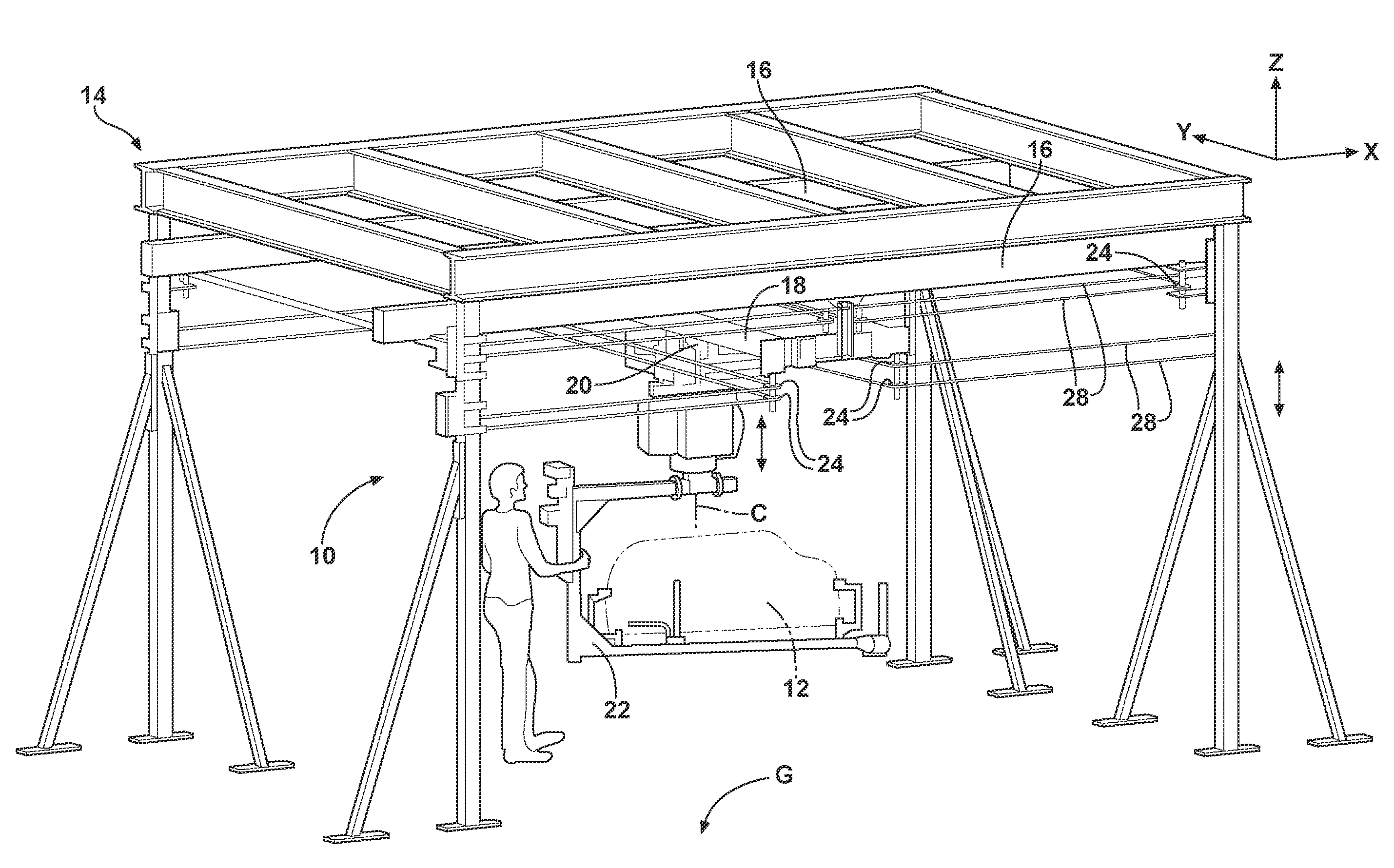
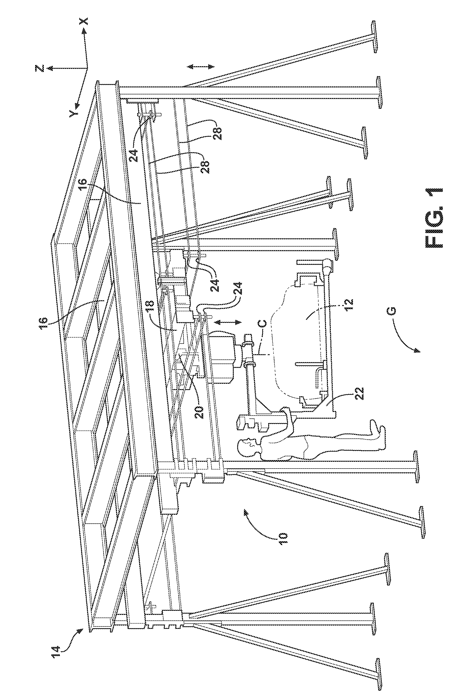
[0015]Referring to the drawings, wherein like reference numbers refer to like components, an actuation system 10 configured for moving a payload 12 in a plurality of directions is shown at 10 in FIG. 1. The actuation system 10 is mounted to a stationary support structure 14 that is configured to support the actuation system 10 and the payload 12. The support structure 14 includes, but is not limited to a pair of parallel rails 16 or runway tracks.

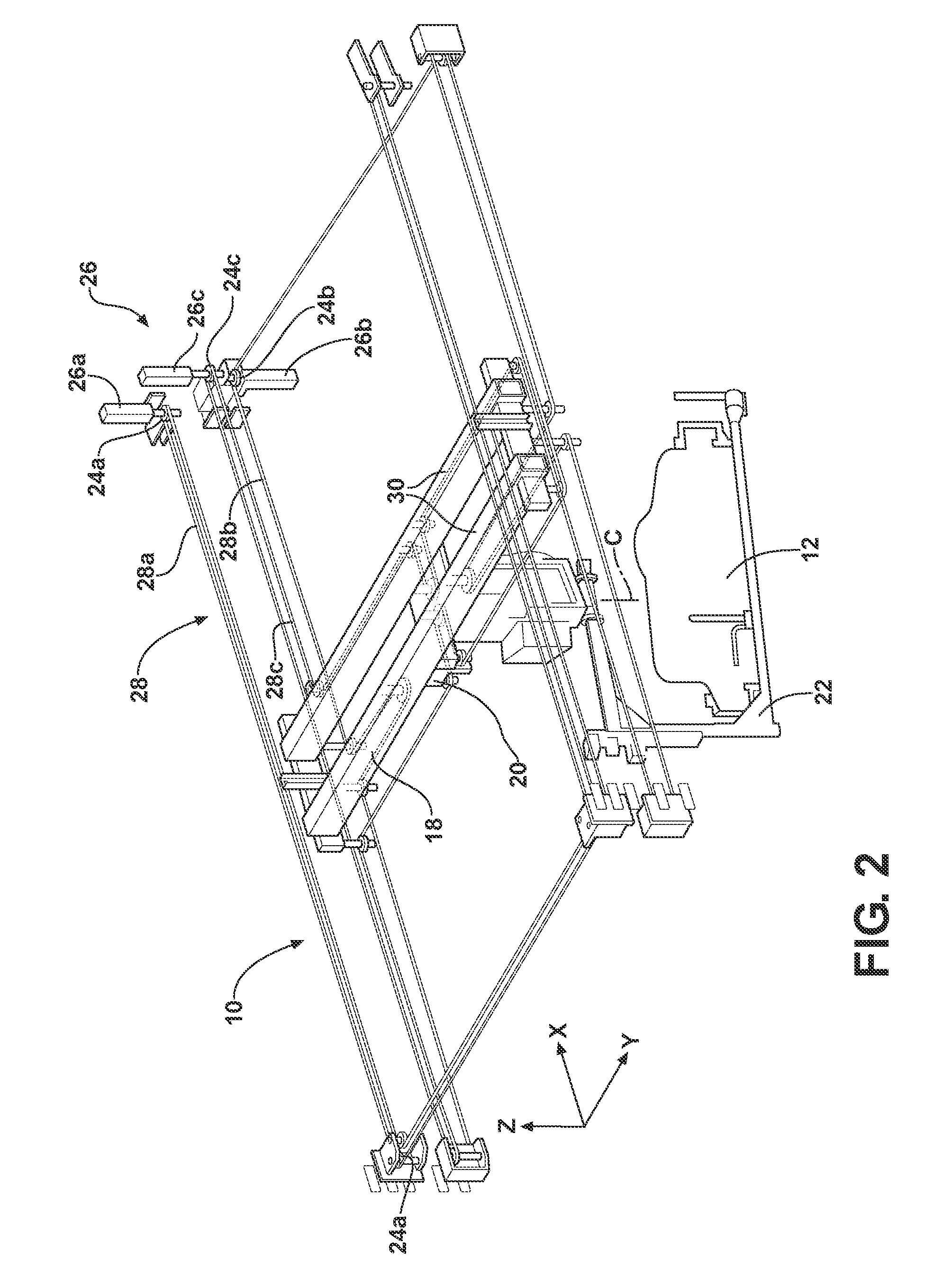
[0016]Referring to FIG. 2, the actuation system 10 includes a bridge crane 18, a trolley 20, an end effector 22, a plurality of pulleys 24, a plurality of actuators 26, and a plurality of belts 28. The bridge crane 18 is a structure that includes at least one girder 30 that spans the pair of parallel rails 16. The bridge crane 18 is adapted to carry the payload 12 along an X axis. The trolley 20 is movably attached to the girders 30 of the bridge crane 18 such that the trolley 20 is adapted to carry the payload 12 along a Y axis, in general...


PUM


Abstract

An actuation system includes a bridge crane, a trolley, and an end effector and is configured for moving a payload. A first actuator is operatively connected to the bridge crane. The bridge crane is configured for moving along an X axis in response to the first actuator being actuated. The trolley extends from the bridge crane. A second actuator is operatively connected to the trolley. The trolley is configured for moving along a Y axis in response to the second actuator being actuated. The end effector extends from the trolley and is configured for supporting a payload. A third actuator is operatively connected to the end effector. The end effector is configured for rotating about the Z axis in response to the third actuator being actuated to rotate the end effector. Each actuator is disposed in spaced relationship to the bridge crane, the trolley, and the end effector.

Description

TECHNICAL FIELD[0001]The present invention relates to an actuation system that is configured for moving a payload.BACKGROUND OF THE INVENTION[0002]Overhead bridge cranes are widely used to lift and relocate large payloads. Generally, the displacement in a pick and place operation involves three translational degrees of freedom and a rotational degree of freedom along a vertical axis. This set of motions, referred to as a Selective Compliance Assembly Robot Arm (“SCARA”) motions or “Schönflies” motions, is widely used in industry. A bridge crane allows motions along two horizontal axes. With appropriate joints, it is possible to add a vertical axis of translation and a vertical axis of rotation. A first motion along a horizontal axis is obtained by moving a bridge on fixed rails while the motion along the second horizontal axis is obtained by moving a trolley along the bridge, perpendicularly to the direction of the fixed rails. The translation along the vertical axis is obtained usi...

Claims


Application Information

Patent Timeline
IPC IPC(8): B66C11/16B66C17/00B66C9/14B66C19/00
CPCB25J9/026B25J9/104B66C1/445B66C13/30B66C11/16B66C13/06B66C9/14
Inventor LALIBERTE, THIERRYGOSSELIN, CLEMENTFOUCAULT, SIMONMAYER-ST-ONGE, BORISGAO, DALONGSCHEUERMAN, ROBERT J.
Owner UNIV LAVAL
Learn More