Electric fan

a technology of electric fans and fans, applied in the direction of non-positive displacement fluid engines, pump components, piston pumps, etc., can solve the problems of still too concentrated airflow and blowing light objects around, and achieve the effect of gentle airflow

Inactive Publication Date: 2011-06-02
CHEN I HUANG
View PDF34 Cites 2 Cited by
  • Summary
  • Abstract
  • Description
  • Claims
  • Application Information

AI Technical Summary

Benefits of technology

[0007]The main object of the present invention is to provide an electric fan that provides gentle airflow.

Problems solved by technology

However, this creates a tunnel effect, where a strong and concentrated channel of air is produced, which is uncomfortable and blows light objects around.
Although the conventional electric fan can be control to rotate and provide week airflow, the airflow still too concentrated.

Method used


Image

  • Electric fan
  • Electric fan
  • Electric fan

Examples


Embodiment Construction

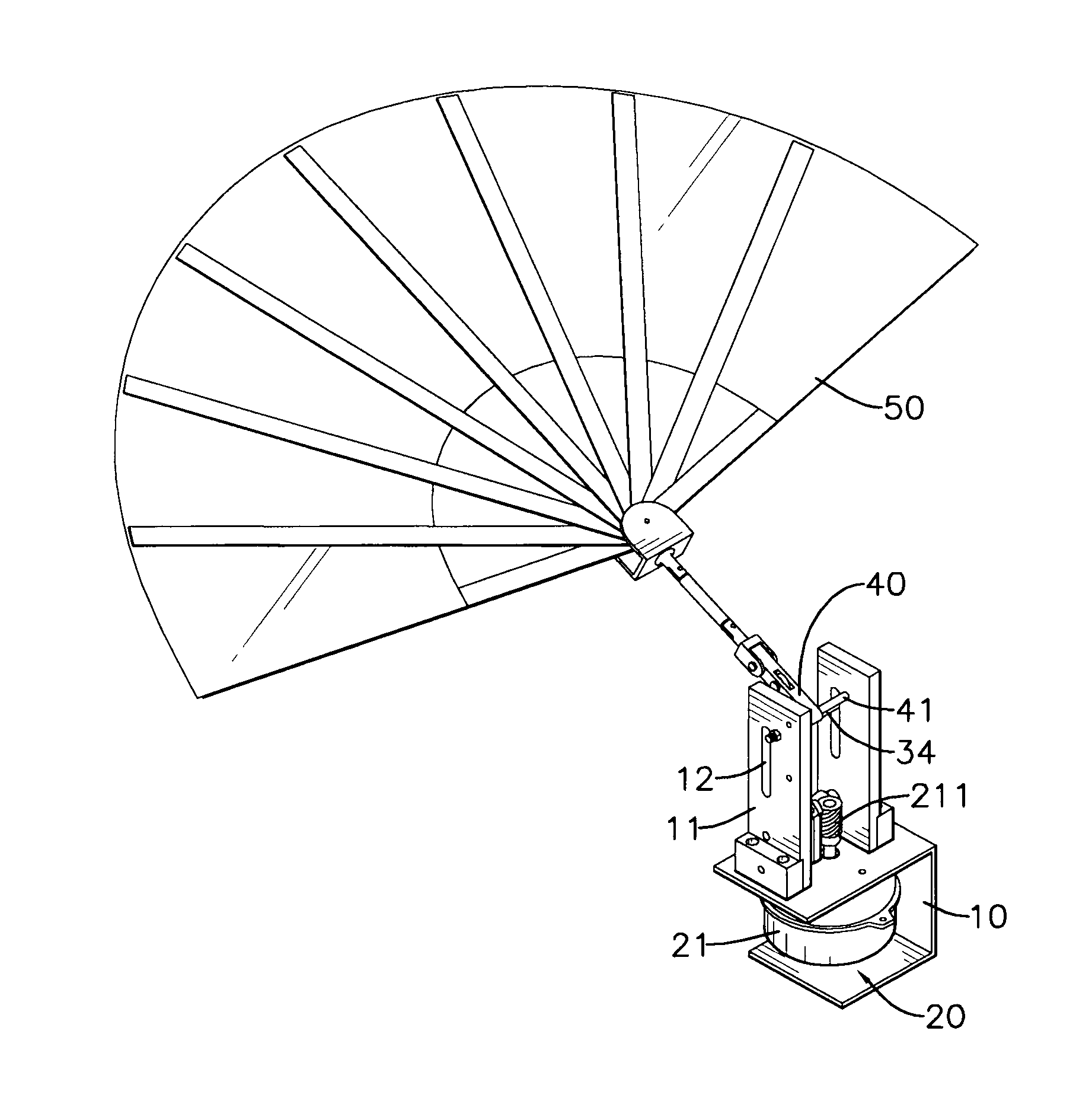
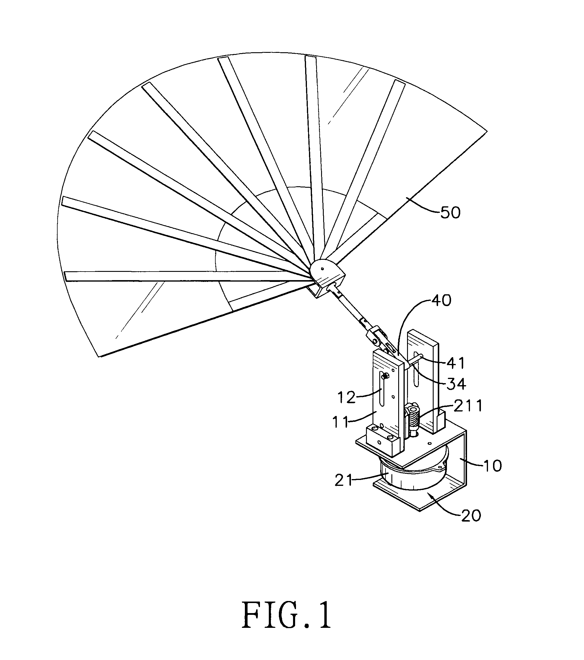
[0017]With reference to FIGS. 1 and 2, an electric fan in accordance with the present invention comprises a bracket (10), a transmission assembly (20), a linking assembly (30), a swing object (40) and a fan (50).

[0018]The bracket (10) has two stands (11) being parallel to each other. At least one of the stands (11) has a slot (12) formed longitudinally through the stand (11).

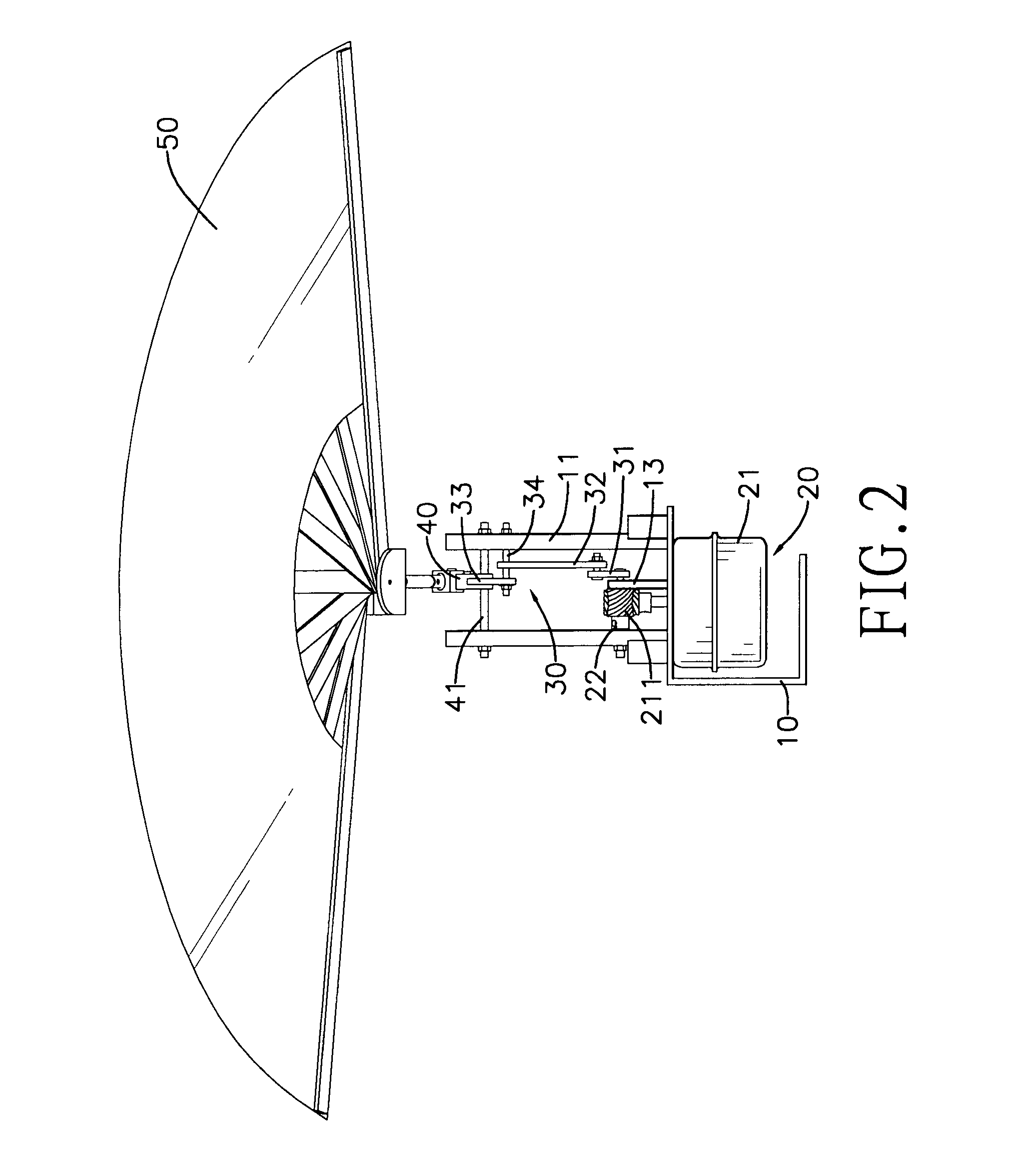
[0019]The transmission assembly (20) is mounted on the bracket (10) and has a motor (21) and a driven unit (22). The motor (21) has an output shaft (211) protruding between the stands (11). The output shaft (211) may be a worm rod. The driven unit (22) is attached rotatably to the bracket (10), is connected to and drove by the output shaft (211) and may have a worm gear engaging the output shaft (211).

[0020]With further reference to FIG. 3, the linking assembly (30) is connected to the transmission assembly (20) and has at least one bottom linking rod (31), at least one middle linking rod (32), a top linking rod...


PUM


Abstract

An electric fan has a bracket, a transmission assembly, a linking assembly, a swing object and a fan. The transmission assembly is mounted on the bracket. The linking assembly is connected to the transmission assembly. The swing object is connected pivotally to the linking assembly. The fan is connected to the swing object. The transmission assembly is actuated to drive the fan to swing up and down and provide gentle and sustained airflow so users can feel truly comfortable.

Description

BACKGROUND OF THE INVENTION[0001]1. Field of the Invention[0002]The present invention relates to an electric fan, and more particularly to an electric fan that provides gentle airflow.[0003]2. Description of the Prior Arts[0004]An electric fan circulates air for improved comfort.[0005]A conventional electric fan has a motor driving a rotor to move the air. However, this creates a tunnel effect, where a strong and concentrated channel of air is produced, which is uncomfortable and blows light objects around. Although the conventional electric fan can be control to rotate and provide week airflow, the airflow still too concentrated.[0006]To overcome the shortcomings, the present invention provides an electric fan to mitigate or obviate the aforementioned problems.SUMMARY OF THE INVENTION[0007]The main object of the present invention is to provide an electric fan that provides gentle airflow.[0008]An electric fan comprises a bracket, a transmission assembly, a linking assembly, a swing...

Claims


Application Information

Patent Timeline
Patent Type & Authority Applications(United States)
IPC IPC(8): F04D25/06F04D29/26
CPCF04D33/00
Inventor CHEN, I-HUANG
Owner CHEN I HUANG
Why Eureka
Try Eureka