Screen unit

a screen and unit technology, applied in the field of screen units, can solve the problems of reducing the uniformity of screen tension applied, affecting the flatness of the screen, and easily unstable support of the screen, so as to achieve the effect of reducing the bending of the second supporting portion more effectively

Inactive Publication Date: 2011-06-09
SEIKO EPSON CORP
View PDF14 Cites 52 Cited by
  • Summary
  • Abstract
  • Description
  • Claims
  • Application Information

AI Technical Summary

Benefits of technology

[0027]According to this structure, the first supporting portion and the second supported portion are supported by the first conn...

Problems solved by technology

According to the structure which supports the upper end portion of the screen at one point around the center of the screen, the left and right ends of the upper end portion of the screen easily bend in the downward directi...

Method used


Image

  • Screen unit
  • Screen unit
  • Screen unit

Examples


first embodiment

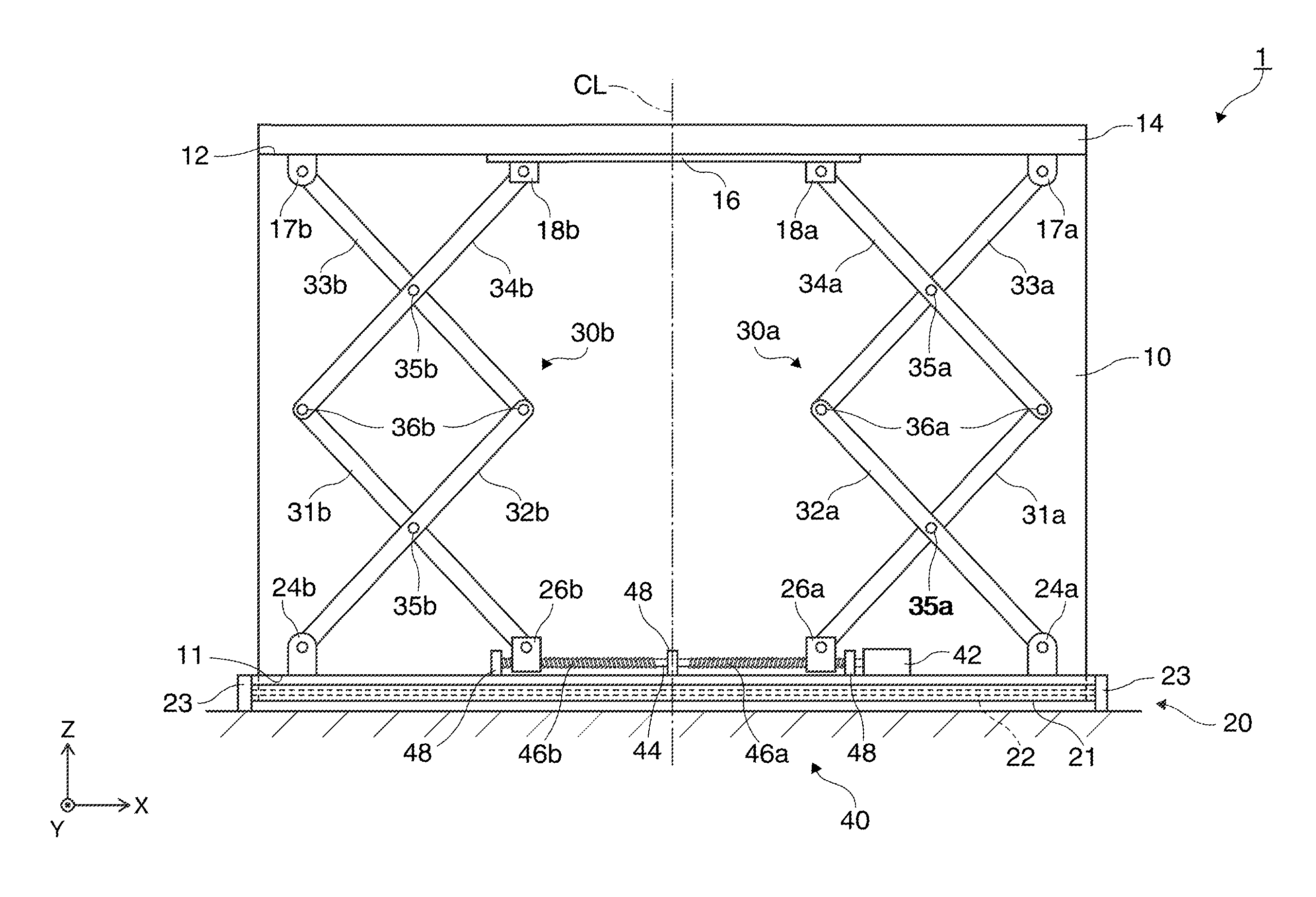
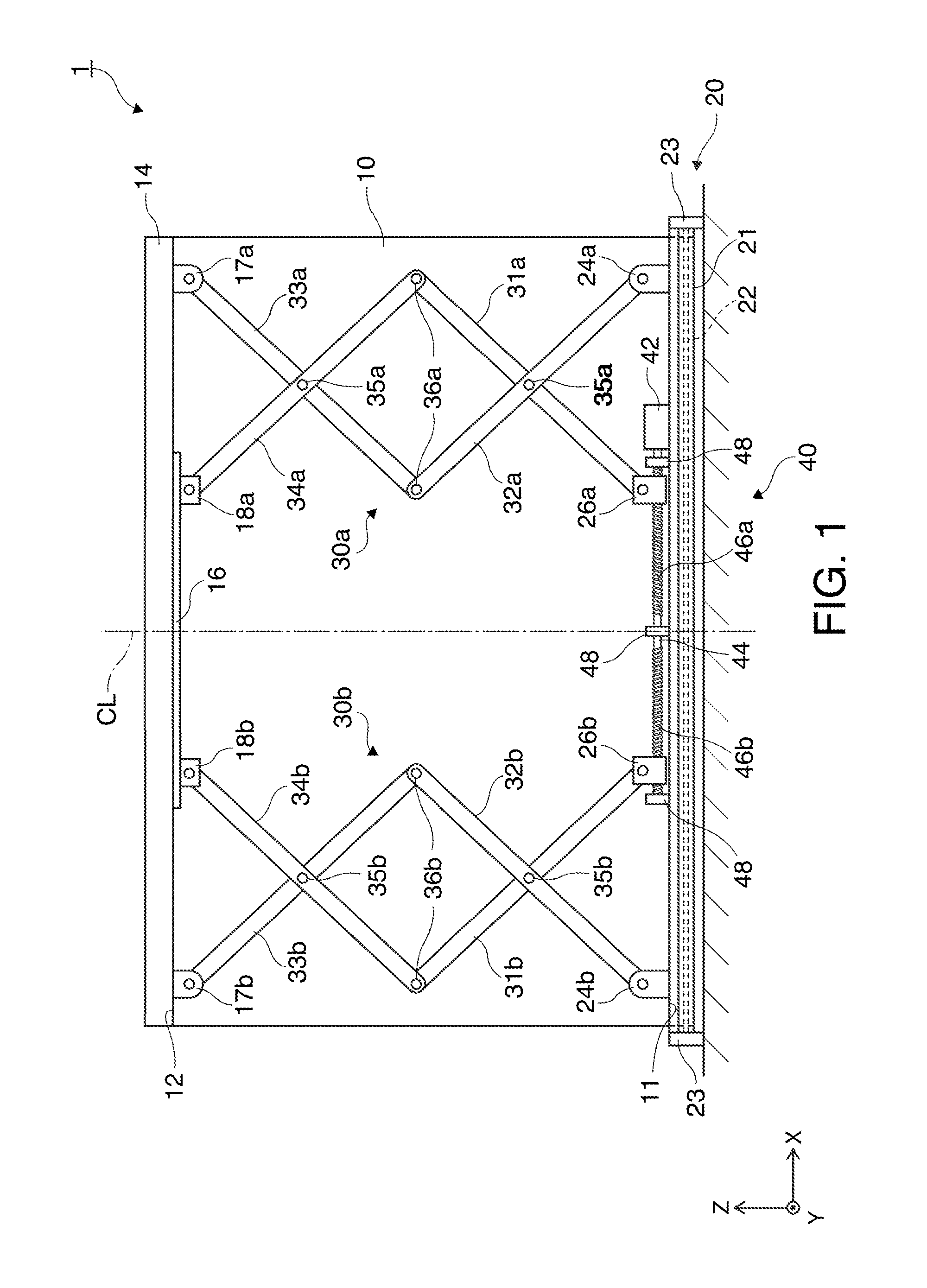
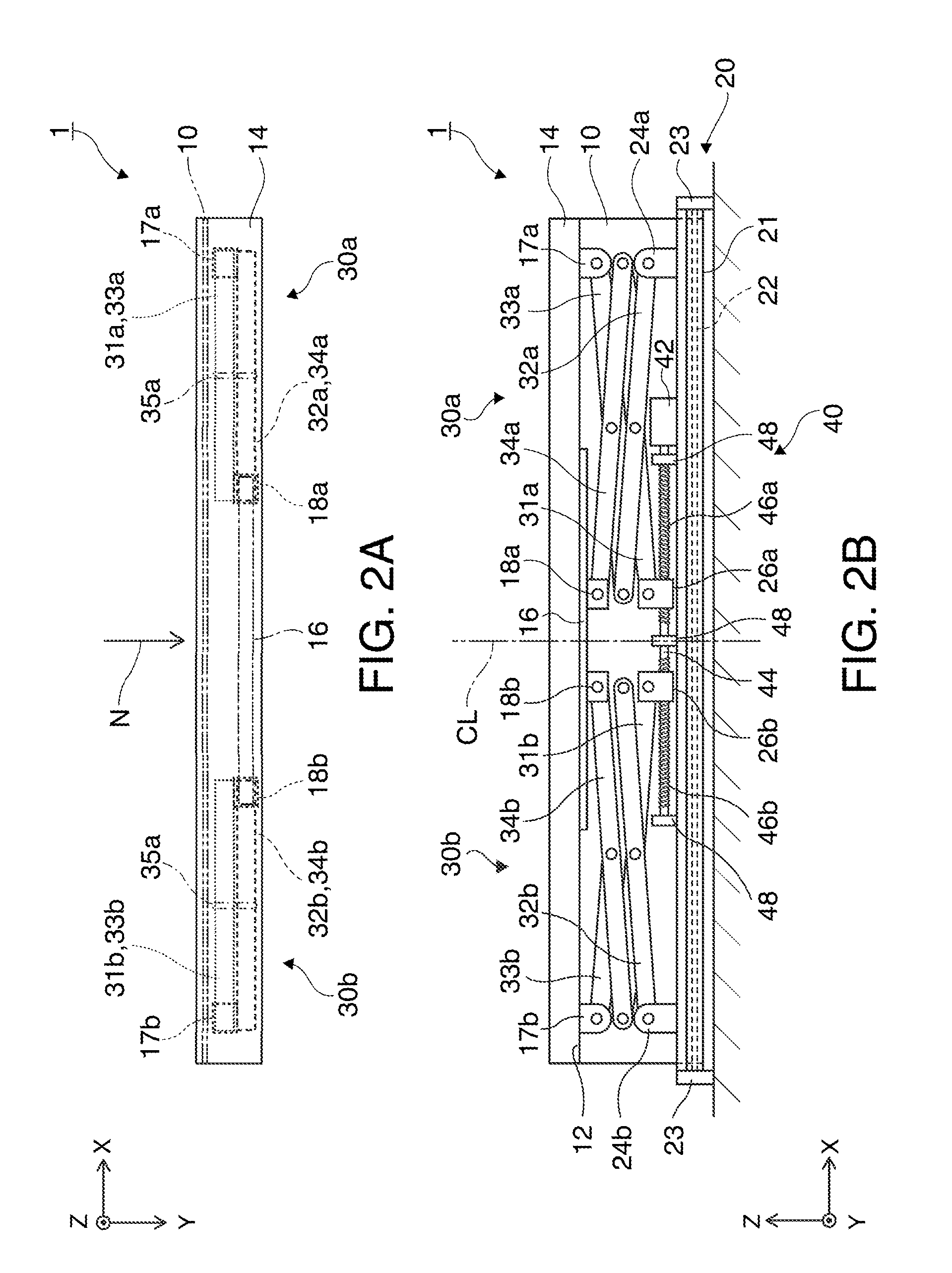
[0038]A screen unit according to a first embodiment is now described with reference to FIGS. 1, 2A and 2B, and 3A through 3C. FIGS. 1, 2A and 2B illustrate the general structure of the screen unit according to the first embodiment. More specifically, FIG. 1 schematically illustrates the screen unit in an expanded condition as viewed from the back. FIG. 2A schematically illustrates the screen unit in the expanded condition as viewed from above. FIG. 2B schematically illustrates the screen unit in a stored condition as viewed from the back. FIGS. 3A through 3C illustrate a rotating mechanism according to the first embodiment. More specifically, FIG. 3A is a perspective view showing the structure of a main part of the rotating mechanism, and FIGS. 3B and 3C illustrate the operation of the rotating mechanism.

[0039]As illustrated in FIG. 1, a screen unit 1 according to the first embodiment includes a screen 10, a storing portion 20 as a first supporting portion, a supporting portion 14 a...

second embodiment

[0087]A screen unit according to a second embodiment is now described with reference to the drawings. FIG. 4 illustrates the general structure of the screen unit in the second embodiment. More specifically, FIG. 4 schematically illustrates a main part of the screen unit as viewed from the back.

[0088]The screen unit in the second embodiment has a structure similar to that of the screen unit in the first embodiment except for the structure of the rotating mechanism. Common reference numbers are given to parts and components common to those in the first embodiment, and the same explanation of the common parts and components is not repeated.

[0089]The structure of a screen unit 2 according to the second embodiment is now explained with reference to FIG. 4. The screen unit 2 in the second embodiment is a screen unit installed on the floor surface. The screen unit 2 includes the screen 10 (see FIG. 1), the storing portion 20, the supporting portion 14 (see FIG. 1), a pair of the connecting...

third embodiment

[0101]A screen unit according to a third embodiment is now described with reference to the drawings. FIG. 5 illustrates the general structure of the screen unit in the third embodiment. More specifically, FIG. 5 schematically illustrates a main part of the screen unit as viewed from the back.

[0102]The screen unit in the third embodiment has substantially the same structure as that of the screen unit in the second embodiment except for a rotating mechanism suited for installation on the ceiling surface. Common reference numbers are given to parts and components common to those in the second embodiment, and the same explanation of the common parts and components is not repeated.

[0103]The structure of a screen unit 3 according to the third embodiment is now explained. The screen unit 3 in the third embodiment is a screen unit installed on the ceiling surface. The screen unit 3 includes the screen 10 (see FIG. 1), the storing portion 20, the supporting portion 14 (see FIG. 1), a pair of...


PUM


Abstract

A screen unit includes: a screen which has a first side and a second side opposing to each other in a first direction and extending substantially in parallel with each other; a first supporting portion extending along the first side to support the first side; a second supporting portion extending along the second side to support the second side; and a plurality of connecting mechanisms each of which extends between the first supporting portion and the second supporting portion, and expands and contracts in the first direction to move the second supporting portion close to and away from the first supporting portion, wherein the plurality of connecting mechanisms are disposed in parallel with the first supporting portion, and are located almost linearly symmetric with respect to a center line connecting approximately the center of the first side and approximately the center of the second side.

Description

BACKGROUND[0001]1. Technical Field[0002]The present invention relates to a screen unit.[0003]2. Related Art[0004]A screen unit of a type currently known expands a screen on which an image is projected from a projection type display apparatus such as a projector when the screen is used, and stores the screen when the screen is not used. This type of screen unit uses a pantograph-shaped connecting mechanism in many cases which has a plurality of arms connected with each other as a mechanism for shifting the screen upward and downward at the time of expansion and storage of the screen and for supporting the screen in an expanded condition.[0005]An example known as a structure of this connecting mechanism has arms connected in a rhomboidal shape and supporting the upper end portion of the screen at one point around the center of the screen. Also, such a structure which has arms crossing each other substantially in an X shape for connection with each other and supporting two points of th...

Claims


Application Information

Patent Timeline
IPC IPC(8): A47G5/00G03B21/56G03B21/58
CPCG03B21/58
Inventor KUROI, KIYOSHIHASHIZUME, HIDETOSHI
Owner SEIKO EPSON CORP
Why Eureka
Try Eureka