Method of manufacturing ground-burial type solid insulated transformer

a technology of solid insulation transformer and manufacturing method, which is applied in the direction of manufacturing tools, magnetic bodies, instruments, etc., can solve the problems of not having resistance to natural chemical reaction, limited to transformers with relatively low power, and prior art of solid type or dry type transformers or methods of manufacturing the same have problems, so as to achieve stable configuration and avoid corrosion

Active Publication Date: 2011-06-23
CHERYONG ELECTRIC
View PDF5 Cites 6 Cited by
  • Summary
  • Abstract
  • Description
  • Claims
  • Application Information

AI Technical Summary

Benefits of technology

[0013]In addition, windings are surrounded by the shell and silicone or high molecular compound and thus mechanically stable configur

Problems solved by technology

Here, a dry type transformer using gas such as circulating air as dielectric material is classified as ground-type and underground-type, which generally raise drawbacks of not having resistance against natural chemical reaction when exposed to ground or underground surrounding.
The manufacturing of the solid type or dry type transformer has been succeeded but is limited to transformer with relatively low power.
Furthermore, the prior art of solid type or dry type transformer or a method of manufacturing of the same has some problems as follows.
First, in case of the prior art of the solid type or dry type transformer the thermal diffusion through solid type dielectric material is limited and the accumulated heat inside windings can produced hot spots or high thermal gradients that can lead to cracks and produce electrical arcs in the solid insulation system.
In particular, in some cases, the breakdown of the solid insulation of the transformer may lead to transformer failure to operate properly.
The cracks produced in the transformer can make the transformer mechanically unstable (breakage of transformer coils) which can lead to further break down of the dielectric media between coils and within core or within coils.
The electric arc produced within the solid insulation material weakens the dielectric strength of the solid type insulation material, causing break down of the solid insulation system leading to severe damages or even

Method used


Image

  • Method of manufacturing ground-burial type solid insulated transformer
  • Method of manufacturing ground-burial type solid insulated transformer
  • Method of manufacturing ground-burial type solid insulated transformer

Examples


Embodiment Construction

[0027]The preferred embodiments of a manufacturing method of a ground-buried type solid insulation transformer according to the present invention will be described in detail referring to the accompanied drawings. However, it has to be understood that the present invention is not limited to the provided embodiments without departing from a spirit of the present invention.

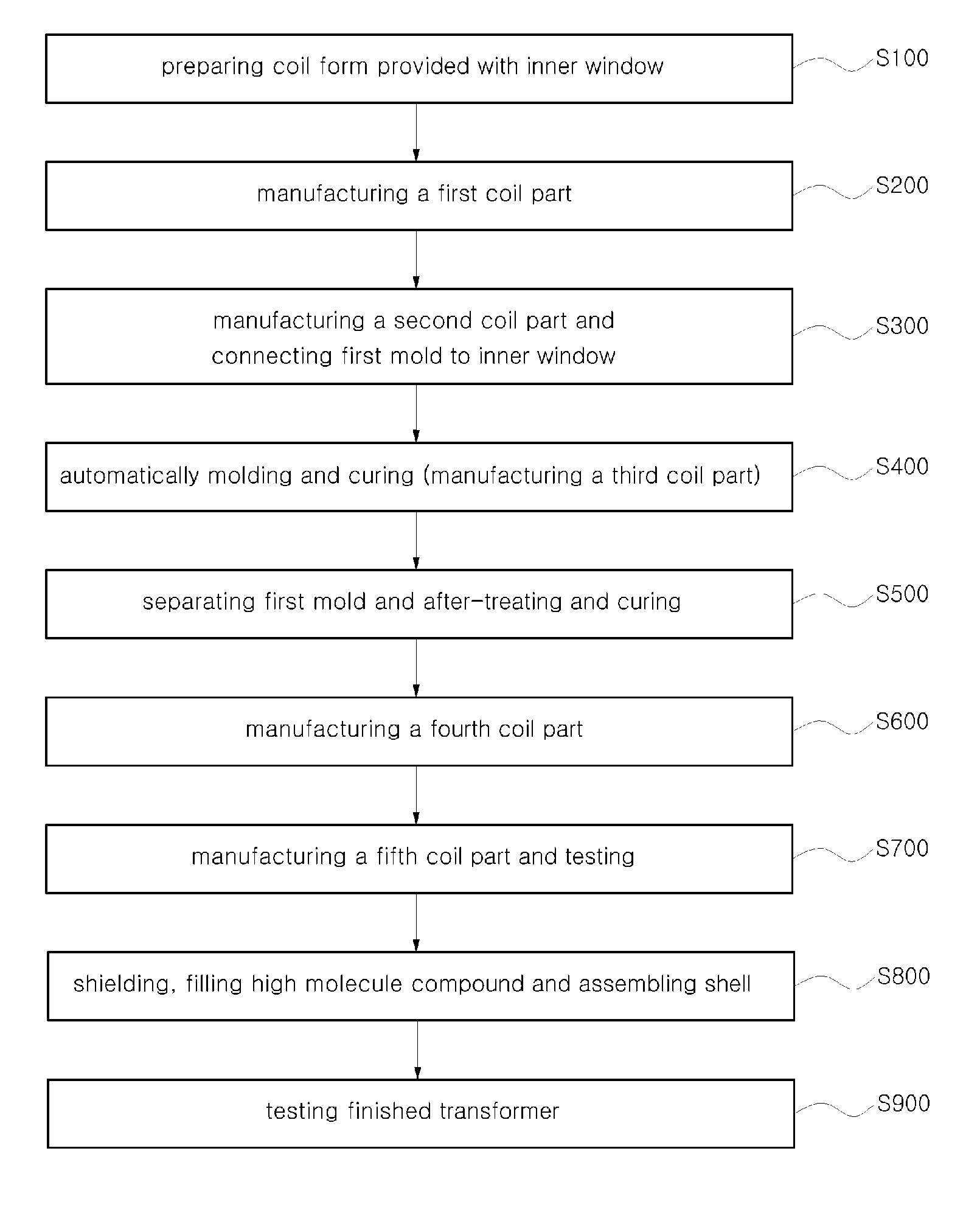
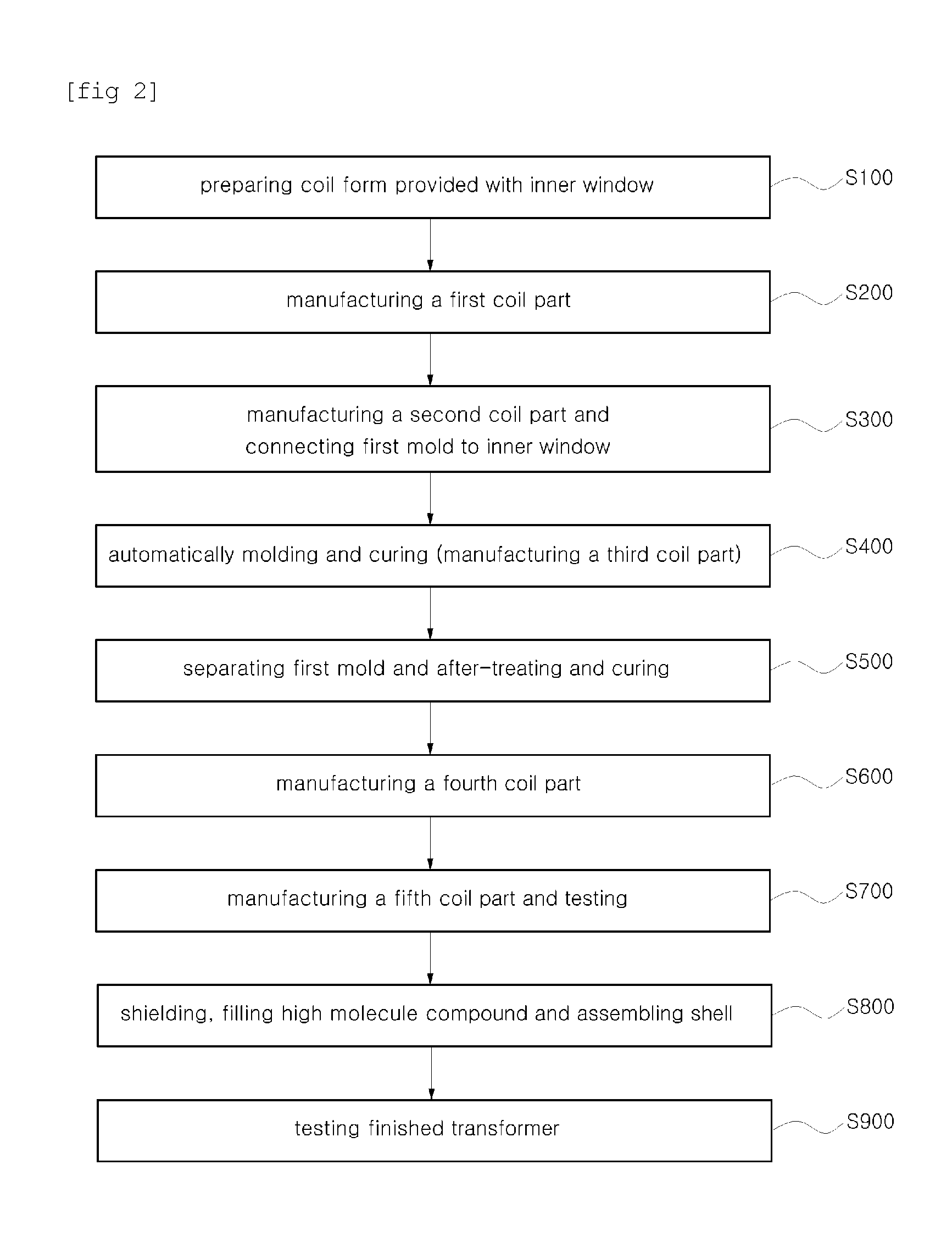
[0028]Referring again to accompanied drawings, FIG. 2 shows schematically a processing order of a manufacturing method of ground-buried type solid insulation transformer according to one embodiment of the present invention. Referring to FIG. 2, the manufacturing method of a ground-buried type solid insulation transformer includes nine processes (S100-S900). That is, each process of the nine processes (S100-S900) is as follows:

[0029]Through a first process S100 a coil form 10 is provided in which an inner window 11 is formed.

[0030]Through a second process S200 a low voltage coil 20 and a high voltage coil 21 are wound...


PUM

PropertyMeasurementUnit
Temperatureaaaaaaaaaa

Abstract

A manufacturing method of ground-buried solid type insulation transformer is disclosed. According to the transformer manufactured by the method, electric shock to be given to human and animal that make contact with outer case due to electric field produced from winding wire within solid type insulation transformer, can be avoided, and even in case it is buried underground and it is used underwater for a long time, corrosion thereof can be avoided. The manufacturing method of ground-buried solid type insulation transformer comprises 9 processes in total.

Description

FIELD OF THE INVENTION[0001]The present invention relates to a manufacturing method of a ground-buried type solid insulation transformer, and more particularly, to a manufacturing method of a ground-buried type solid insulation transformer in which solid is used as dielectric medium instead of liquid or gas.BACKGROUND OF THE INVENTION[0002]Generally, it has been well known in the art that each of primary winding and secondary winding (coils) of a dry type transformer is treated with solid type cast material in order to provide a dry type transformer in which dielectric liquid or gas is used as an electrical insulating medium and for diffusing heat created in the windings (coils) or in the transformer core.[0003]In addition, an oil-filled transformer using liquid such as oil as dielectric material as an electrical insulating medium and for diffusing heat created in the windings (coils) or in the transformer core, classified as above-ground-type, overhead-type and underground-type, et...

Claims


Application Information

Patent Timeline
IPC IPC(8): H01F7/06
CPCH01F27/362H01F30/10H01F41/005Y10T29/49071Y10T29/49078Y10T29/49069Y10T29/4902H01F41/127H01F27/36H01F27/363H01F27/28H01F27/24H01F27/00
Inventor PARK, JONG TAESONG, BYUNG KWONHWANG, KEE HAKIM, TAE HOYI, KI HAK
Owner CHERYONG ELECTRIC
Why Eureka
Try Eureka