Cable Gland

a cable gland and cable technology, applied in the field of cable glands, can solve the problems of predetermined position, difficult fitting process, and rotating the cable gland for fixing, and achieve the effect of more fitting process

Inactive Publication Date: 2011-06-23
EBM PAPST MULFINGEN GMBH & CO KG
View PDF12 Cites 19 Cited by
  • Summary
  • Abstract
  • Description
  • Claims
  • Application Information

AI Technical Summary

Benefits of technology

[0003]A cable gland such as this is already known from the document DE 9406382 U1. In this cable gland, two parts which can rotate with respect to one another, a cable adapter and a screw-on connecting stub, are fixed axially by snap-action or latching connections and are fixed in a predetermined rotation position by a latching device. One disadvantage of this embodiment is that the rotation position is predetermined by the latching device. A second disadvantage is that the cable gland must be rotated for fixing. Depending on the spatial circumstances in the vehicle and on t...

Problems solved by technology

One disadvantage of this embodiment is that the rotation position is predetermined by the latching device.
A second disadvantage is that the cable gland must be rotated for fixing.
Depending on the spatial circumstances in the vehicle and on the alignment of the cable connection and the position of the housing, these disadvantages can make the fitting process more difficult.
In addition, an embodiment such as ...

Method used


Image

  • Cable Gland
  • Cable Gland
  • Cable Gland

Examples


Embodiment Construction

[0020]The same parts are identified by the same reference symbols in FIGS. 1 to 7.

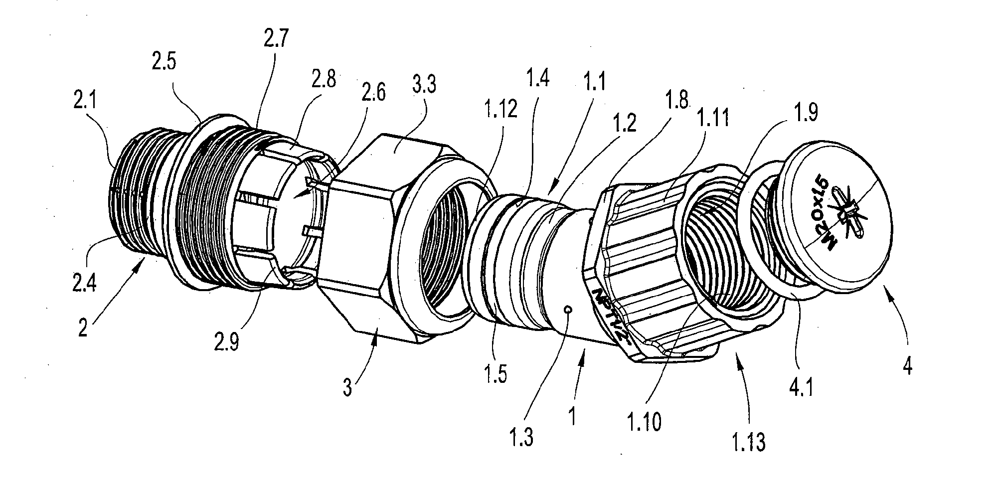
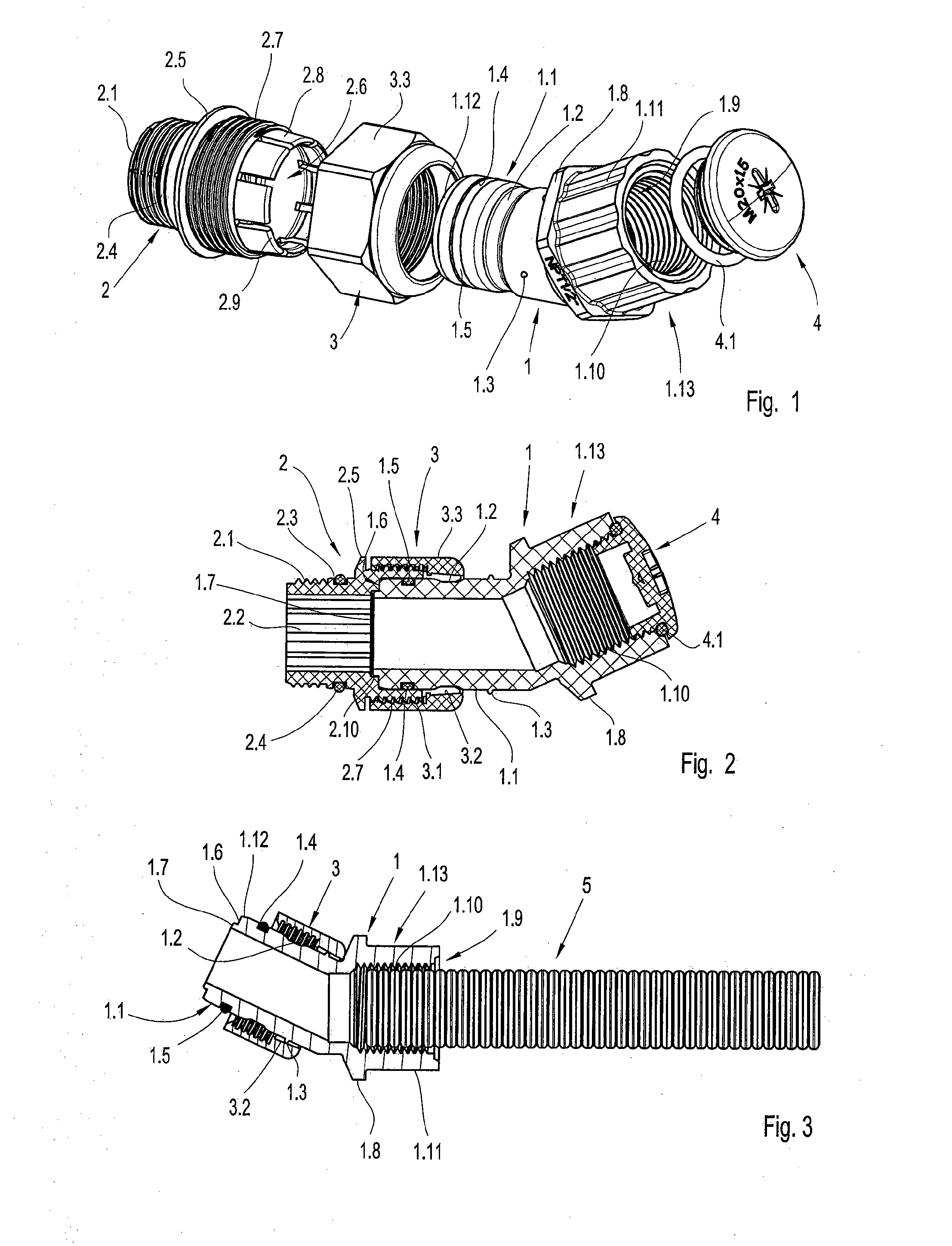
[0021]By way of example, FIG. 1 and FIG. 2 show a cable gland according to the invention which comprises a cable adapter 1, a screw-in connecting stub 2, a union nut 3, a closure screw 4 and a plurality of O-ring seals 1.5, 2.4, 4.1.

[0022]The screw-in connecting stub 2 is hollow-cylindrical and has two housing sections which are split by a contact wall 2.5, which runs on the external circumference, and have a through-opening. In the housing section facing away from the cable adapter 1, the screw-on connecting stub 2 has a screw-on thread 2.1 on its external circumference and, between the screw-on thread 2.1 and the contact wall 2.5, it has a circumferential groove 2.3 with an O-ring seal 2.4. The O-ring seal 2.4 seals the connection between the screw-on connecting stub 2 and an attachment housing which is not illustrated. In addition, an internal polygonal contour 2.2 is located on the internal circumf...


PUM


Abstract

The present invention relates to a cable gland for an electronics housing (6) of an electric motor, comprising a cable adapter (1) and a screw-on connecting stub (2), which can be screwed to a housing, for attachment of a cable connection. Fixing means (3, 2.8) which are arranged on the cable adapter (1) and on the screw-on connecting stub, allowing, in an assembly position, an axial insertion of the cable adapter (1) into the screw-on connecting stub (2) in any desired rotation position relative to one another and in an inserted state, allowing alignment of the rotation position of the cable adapter (1) relative to the screw-on connecting stub (2) and in a fixing position, fixing the cable adapter (1) axially and in the respective relative rotation position to the screw-on connecting stub (2).

Description

CROSS REFERENCE TO RELATED APPLICATION[0001]This application claims priority to European Patent Application No. 0 916 2864.4, filed Jun. 16, 2009.FIELD OF THE INVENTION[0002]The subject matter of the invention is a cable gland for an electronics housing of an electric motor having a through-opening, comprising a cable adapter and a screw-on connecting stub for attaching a cable connection to a housing, for example for attaching a cable harness to an electronics housing of an electric motor. The invention likewise includes an electronics housing of an electric motor having a cable gland such as this.BACKGROUND AND SUMMARY OF THE INVENTION[0003]A cable gland such as this is already known from the document DE 9406382 U1. In this cable gland, two parts which can rotate with respect to one another, a cable adapter and a screw-on connecting stub, are fixed axially by snap-action or latching connections and are fixed in a predetermined rotation position by a latching device. One disadvanta...

Claims


Application Information

Patent Timeline
IPC IPC(8): H02G3/06
CPCH02G3/0633H02G3/22H02G3/0691H02G3/0675H02K5/225H02K7/14
Inventor BEST, DIETER
Owner EBM PAPST MULFINGEN GMBH & CO KG
Why Eureka
Try Eureka