Water delivery device

Active Publication Date: 2011-06-30
DELTA FAUCET
35 Cites 24 Cited by

AI-Extracted Technical Summary

Problems solved by technology

This sensor arrangement works well for sensing objects that produce diffuse return signals such as hands or plastic objects, but have difficulty with highly polished or smooth object such as metal or glass.
Two primary issues with the sensing of shiny object or objects in water is that the distance reading have significant error or there is a large percentage of noise/instability in the readings.
The...

Benefits of technology

[0017]In another example, the step of determining the presence of the object in the detection zone includes the steps of determining a location of the object in the detection zone; and determining a confidence level for the object. In a variation thereof, the method further comprising the step of establishing a baseline position based on the optical energy received from the detection zone. In a further variation thereof, the step of automatically configuring the valve in the first arrangement is performed when the location of the object in the detection zone is less than the baseline position and the confidence level exceeds a threshold value. In yet another variation thereof, the step of determining the location of the object in the detection zone includes the steps of correlating the received optical energy with a comb function to produce a correlated result; and selecting a pixel in the correlated result which has the highest intensity, the pixel representing the location of the object in the detection zone. In still a further variation thereof, the step of determining a confidence level for the object includes the steps of correlating the received optical energy with a comb function to produce a correlated result; identifying a first pixel in the correlated result which has the corresponding highest peak intensity of the correlated result; identifying a second pixel in the correlated result which has the corresponding second highest peak intensity of the correlated result; and classify the object based on at least one of a first comparison of the intensity values of the first pixel and the second pixel and a second comparison of a separation of the first pixel and the second pixel. In a f...

Abstract

A proximity sensor is disclosed. The proximity sensor may be incorporated as part of a water delivery device. A holder which aligns an optical source and sensor of the proximity sensor is disclosed.

Application Domain

Operating means/releasing devices for valvesDomestic plumbing +3

Technology Topic

Water deliveryEngineering +2

Image

  • Water delivery device
  • Water delivery device
  • Water delivery device

Examples

  • Experimental program(1)

Example

DETAILED DESCRIPTION OF THE DRAWINGS
[0047]The embodiments of the invention described herein are not intended to be exhaustive or to limit the invention to the precise forms disclosed. Rather, the embodiments elected for description have been chosen to enable one skilled in the art to practice the invention.
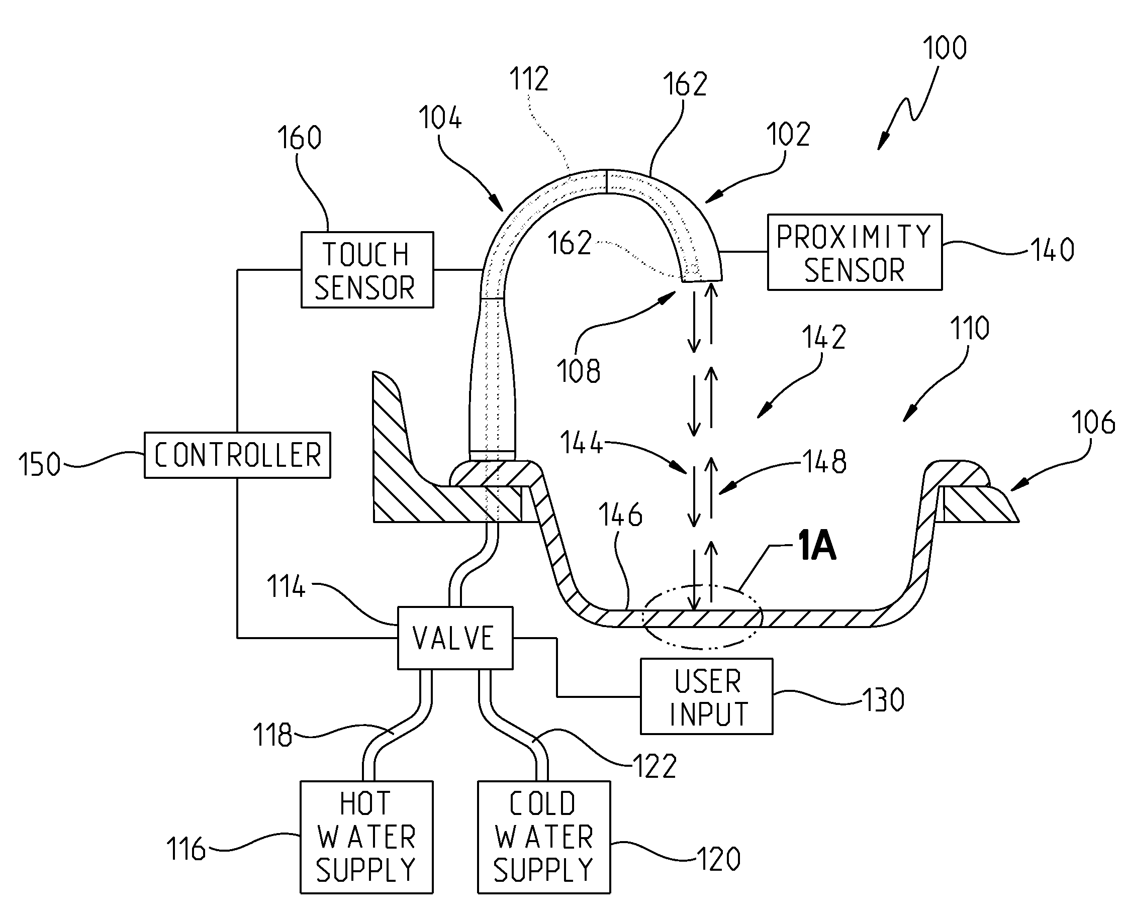
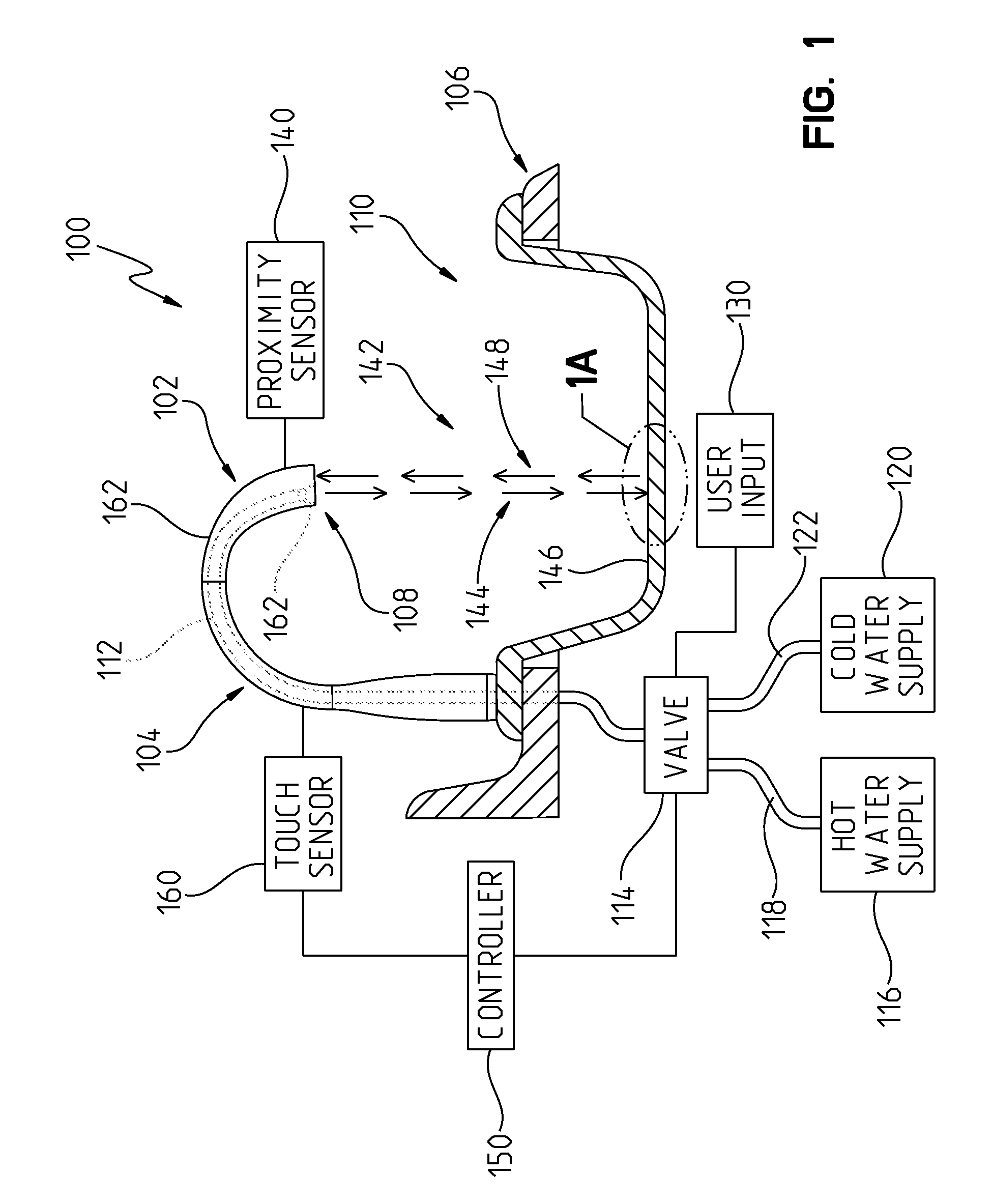
[0048]Referring to FIG. 1, an exemplary water delivery device 100 is shown. The water delivery device 100 is a faucet 102 having an elongated spout 104. Although a faucet 102 is illustrated other water delivery devices are contemplated, including shower systems; pot fillers; and any other device which controls the provision of water.
[0049]Faucet 102 is mounted to a sink deck 106 and a first end 108 of spout 104 is positioned over a sink basin 110. Faucet 102 includes at least one fluid conduit 112 which is in fluid communication with at least one valve 114. The valve 114 is further in fluid communication with a hot water supply 116 through a fluid conduit 118 and a cold water supply 120 through a fluid conduit 122. Valve 114 may be a single valve or a combination of multiple valves.
[0050]In one embodiment, valve 114 is an electronic mixing valve which receives water from one or both of hot water supply 116 and cold water supply 120 and provides mixed water to fluid conduit 112. Exemplary electronic mixing valves are disclosed in U.S. patent application Ser. No. 11/737,727, filed Apr. 19, 2007, attorney docket DFC-P0028-01, the disclosure of which is expressly incorporated by reference herein. The temperature and flow rate of the mixed water is specified by a user through one or more user inputs 130. Exemplary user inputs include manual inputs and electronic inputs. Exemplary manual inputs include levers, knobs, and other suitable types of mechanically actuated inputs. Exemplary electronic inputs include slide touch controls, buttons, switches, a touch screen interface, and other suitable types of user inputs which generate an electrical signal in response to at least one of a tactile, audio, or optical input. Exemplary electronic inputs are disclosed in U.S. patent application Ser. No. 11/737,727, filed Apr. 19, 2007, attorney docket DFC-P0028-01, U.S. patent application Ser. No. 12/255,358, filed Oct. 21, 2008, attorney docket DFC-P4159, the disclosures of which are expressly incorporated by reference herein.
[0051]In one embodiment, valve 114 is an electronic mixing valve including an ON/OFF valve in series or simply an ON/OFF valve. One reason for including an ON/OFF valve is to provide an easy ON/OFF control without requiring a user to set a desired temperature and flow rate with user inputs 130 each time that faucet 102 is to be activated. In this arrangement, the mixing valve regulates temperature and flow and the ON/OFF valve either communicates water to fluid conduit 112 or does not. In one embodiment, valve 114 includes a first valve which regulates the temperature and flow of water from hot water supply 116 and a second valve which regulates the temperature and flow of water from cold water supply 120. The output of these two valves are mixed and provided to fluid conduit 112. In one example, an ON/OFF valve is included in series. In one embodiment, valve 114 may take the form of any of the valve configurations disclosed in any of the patents, published applications, and pending patent applications incorporated by reference herein.
[0052]In one embodiment, faucet 102 includes a hands-free mode of operation. In this arrangement, a desired temperature and flow rate are set with valve 114 through user inputs 130. Faucet 102 includes a proximity sensor 140 which monitors a detection zone 142 for an object. Proximity sensor 140 emits a monitoring signal 144 which, in general, is reflected by objects in detection zone 142, such as sink bottom 146 in FIG. 1, and returned towards proximity sensor 140 as a detection signal 148. A controller 150 of faucet 102 controls the operation of valve 114 based on the detection signal 148 received by proximity sensor 140. In one embodiment, controller 150 configures valve 114 in a first configuration wherein water is communicated to fluid conduit 112 when a first object is detected in detection zone 142 and configures valve 114 in a second configuration wherein water is not communicated to fluid conduit 112 when the first object is not detected in detection zone 142. In one embodiment, controller 150 analyzes the detection signal 148 to determine a position of the first object, to determine a confidence level that the first object is not a false object, and to configure valve 114 appropriately. In one embodiment, controller 150 may execute any of the processing sequences disclosed in any of the patents, published applications, and pending patent applications incorporated by reference herein which include as part of the processing sequence the hands-free operation of the faucet.
[0053]In the illustrated embodiment, in addition to hands-free operation, faucet 102 also includes a touch sensor 160 which provides the user with simple touch ON and touch OFF control of faucet 102 without having to manipulate user inputs 130. In one embodiment, an exterior 162 of spout 104 forms part of a capacitive touch sensor 160 through which controller 150 is able to provide the user with simple touch ON and touch OFF control of faucet 102 without having to manipulate user inputs 130. In one embodiment, controller 150 may execute any of the processing sequences disclosed in any of the patents, published applications, and pending patent applications incorporated by reference herein which include as part of the processing sequence the operation of the faucet through a capacitive touch sensor, such as including the exterior of the spout as part of the capacitive touch sensor.
[0054]Additional exemplary water delivery devices including hands free operation and/or touch sensors include U.S. Pat. No. 6,962,168; U.S. Pat. No. 7,278,624; U.S. Pat. No. 7,472,433; U.S. Pat. No. 7,537,195; U.S. patent application Ser. No. 11/325,128; U.S. patent application Ser. No. 11/326,989; U.S. patent application Ser. No. 11/734,499; U.S. patent application Ser. No. 11/700,556; U.S. patent application Ser. No. 11/590,463; and U.S. patent application Ser. No. 11/105,900, the disclosures of which are expressly incorporated by reference herein.
[0055]In the illustrated embodiment, spout 104 includes a spray head 162. In one embodiment, spray head 162 provides one of an aerated stream of water and a laminar flow of water. In the illustrated embodiment, spray head 162 includes fluid pathways to produce either a stream of water from fluid outlet 164, a spray of water from fluid outlets 166, or a combination of a stream of water from fluid outlet 164 and a spray of water from fluid outlets 166. In one embodiment, spout 104 supports a diverter valve to provide manual selection of either fluid outlet 164, fluid outlets 166, or both. In one embodiment, controller 150 controls a diverter valve to select either fluid outlet 164 or fluid outlets 166 or both based on an input from user inputs 130. In one example, the diverter valve is positioned below sink deck 106 and fluid conduit 112 is two separate fluid conduits, one in fluid communication with fluid outlet 164 and one in fluid communication with fluid outlets 166. In one example, the diverter valve is positioned within spout 104. In one embodiment, spout 104 includes a pull-out wand portion which may be spaced apart from the remainder of spout 104 while remaining in fluid communication with valve 114. Exemplary diverter valve arrangements and pull-out wands are disclosed in U.S. patent application Ser. No. 11/700,556, filed Jan. 31, 2007, attorney docket DFC-P0060, the disclosure of which is expressly incorporated by reference herein.
[0056]Referring to FIG. 1A, monitoring signal 144 is illustrated. Monitoring signal 144 includes multiple spatially spaced apart regions of optical energy. These regions correspond to individual beams of optical energy. Illustratively, monitoring signal 144 includes five spatially spaced apart regions of optical energy including a center region 170, a first left side region 172, a first right side region 174, a second left side region 176, and a second right side region 178. Although five regions are shown any number of regions may be implemented. In one embodiment, monitoring signal 144 is continuous temporally. In one embodiment, monitoring signal 144 is pulsed temporally.
[0057]As illustrated, first left side region 172 and first right side region 174 are symmetrical about center region 170 and second left side region 176 and second right side region 178 are also symmetrical about center region 170. In one embodiment, the locations of one or more of first left side region 172, first right side region 174, second left side region 176, and second right side region 178 are asymmetrical about center region 170. As illustrated, first left side region 172 and first right side region 174 are spaced apart from center region 170 at a first distance 180 and second left side region 176 and second right side region 178 are spaced apart from first left side region 172 and first right side region 174, respectively, by a second distance 182. In one embodiment, first distance 180 and second distance 182 are generally equal. In one embodiment, first distance 180 and second distance 182 are not generally equal. In one example, second distance 182 is about half the value of first distance 180.
[0058]In one embodiment, the relative spacing between regions 170-178 remains generally constant over the distance from first end 108 of spout 104 down to sink bottom 146 of sink basin 110. In one embodiment, the travel distance of monitoring signal 144 to the sink bottom 146 is up to about 20 inches, a divergence angle between center region 170 and each of first left side region 172 and first right side region 174 is about 2 degrees, a divergence angle between center region 170 and each of second left side region 176 and second right side region 178 is about 3 degrees, first distance 180 is about 0.70 (at a distance of about 20 inches from first end 108 of spout 104) and second distance 182 is about 0.34 (at a distance of about 20 inches from first end 108 of spout 104). Regardless of any absolute change in the spacing of regions 170-178 as they travel away from first end 108 of spout 104, the proportional spacing of regions 170-178 remains constant. When the beams corresponding to regions 170-178 encounter a diffuse object in detection zone 142 they are reflected by the object generally as five spatially spaced apart point sources. When viewed by a detector from a given direction the reflection includes five spatially spaced-apart intensity peaks as discussed herein.
[0059]In one embodiment, the beams which include regions 170-178 are generated by a plurality of optical sources. Each of the optical sources emits a directional beam of optical energy that defines the respective regions 170-178. Exemplary sources include lasers and light-emitting diodes. As explained below with reference to FIGS. 2-5, in the illustrated embodiment regions 170-178 are generated by a single optical source 168 whose output beam 188 is passed through an optical system 190 which splits the output beam 188 into a plurality of spatially spaced apart beams which include regions 170-178.
[0060]Referring to FIG. 2, an exemplary proximity sensor module 200 is shown. Referring to FIG. 3, proximity sensor module 200 includes optical source 168, optical system 190, a sensor 202, a holder 204, a controller 206, an optical window 208, an optical system 210, a housing 212 including a first housing member 214 and a second housing member 216, and a coupler 218. Optical source 168 and optical system 190 form one example of an illumination module which provides the plurality of spatially spaced apart regions 170-178.
[0061]Holder 204 holds both optical source 168 and sensor 202 in a manner that optical source 168 and sensor 202 are properly aligned. Referring to FIG. 4, holder 204 holds sensor 202 at an angle 220 relative to a line 222 normal to the direction of output beam 188 of optical source 168. In one embodiment, the value of angle 220 is about 8 degrees. Sensor 202 is angled to increase the range of distances that may be detected and to increase the separation between regions 170-178 on the face of sensor 202. Returning to FIG. 3, holder 204 includes a plurality of openings 224 which extend from a lower side of holder 204 to an upper side of holder 204. Openings 224 receive the prongs 226 of sensor 202 such that a surface 228 of sensor 202 is held flush against a surface 230 of holder 204.
[0062]Optical source 168 is received in a recess 240 of holder 204 such that a surface 242 of optical source 168 is flush against a surface 244 of holder 204. An exemplary optical source is a light emitting diode (LED). An exemplary LED is Model No. DL3144008S available from Sanyo.
[0063]As illustrated in FIG. 4, optical source 168 is lowered into recess 240 from a top side of holder 204 while prongs 226 of sensor 202 are passed through openings 224 from a bottom side of holder 204. In an alternative embodiment, shown in FIG. 4A, optical source 168 is received into a recess 240′ from the bottom side of holder 204 just like sensor 202. Regardless of the two configurations of holder 204 shown, optical source 168 and sensor 202 are coupled to controller 206. Exemplary methods of coupling optical source 168 and sensor 202 to controller 206 include soldering and other suitable methods for making the appropriate electrical connections between optical source 168 and controller 206 and between sensor 202 and controller 206. As shown in FIG. 4, both the prongs 250 of optical source 168 and prongs 226 of sensor 202 are received in openings 252 and 254 of controller 206, respectively. Controller 206 is located relative to holder 204 through locator pins 260 extending from the top side of holder 204 which are received in respective recesses in controller 206. In one embodiment, a separation between an optical axis 189 of optical source 168 and a center of sensor 202 indicated by location 188B is about 0.48 inches.
[0064]Once optical source 168 and sensor 202 are assembled to controller 206 through holder 204, optical source 168 is aligned relative to sensor 202. This subassembly of optical source 168, sensor 202, holder 204, and controller 206 is assembled relative to first housing member 214 and second housing member 216. Each of first housing member 214 and second housing member 216 include an elongated slot 264 which receives a corresponding tab 266 of holder 204. Referring to FIG. 4, a lower surface 270 of controller 206 is also supported on surface 272 of first housing member 214 and second housing member 216 at both a front end 274 of controller 206 and a rear end 276 of controller 206. In addition, a lower surface 278 of holder 204 is supported by surface 280 of first housing member 214 and second housing member 216.
[0065]As mentioned herein, optical system 190 splits output beam 188 include multiple beams or sources, shown in FIG. 1A as regions 170-178. Optical system 190 includes a plano-convex lens having a diffraction grating 286 positioned on the flat side of the lens. In one embodiment, the diffraction grating 286 is a separate component coupled to lens 284. In one embodiment, diffraction grating 286 is formed as part of lens 284. Optical system 190 is captured between first housing member 214 and second housing member 216 by recess 290 in both of first housing member 214 and second housing member 216. Lens 284 includes a key feature 294 which mates with a key feature 292 extending into recess 290 for first housing member 214. In a similar fashion, optical window 208 is captured between first housing member 214 and second housing member 216 by recess 296. Referring to FIG. 4, first housing member 214 and second housing member 216 define an exit window 298 through which light generated by optical source 168 and passed by optical system 190 and optical window 208 exits proximity sensor module 200 and an entrance window 300 through which light reflected from the environment is received and passes through optical system 210 and is incident on sensor 202. As shown in FIG. 4, optical system 210 is a convex lens 302 which focuses the received light onto sensor 202.
[0066]In one embodiment, output beam 188 has a visible wavelength. In one embodiment, output beam 188 has an invisible wavelength. In one embodiment, output beam 188 has a wavelength of 785 nm. In one embodiment, optical system 210 includes one or more filters to limit the wavelength band of light reaching sensor 202. In one embodiment, optical window 208 includes an anti-fog coating. In one embodiment, optical window 208 is made an optical polymer. An exemplary optical polymer is E48R ZEONEX brand optical polymer available from Zeon Chemicals L.P. located at 4111 Bells Lane in Louisville, Ky. 40211.
[0067]First housing member 214 and second housing member 216 are coupled together through coupler 218. In the illustrated embodiment, coupler 218 is a threaded member which is threaded into a threaded boss 312 of first housing member 214. Other exemplary methods of coupling second housing member 216 to first housing member 214 include mechanical snaps and vibration welding.
[0068]Controller 206 is coupled to controller 150 through one or more electrical wires which are coupled to coupler 308. In one embodiment, controller 206 provides power to optical source 168 and sensor 202, receives the detected illumination pattern 321 (see FIG. 10) from sensor 202, and communicates the detected illumination pattern to controller 150. Referring to FIG. 1B, proximity sensor module 200 is positioned within spout 104 such that exit window 298 and entrance window 300 are aligned with window 310.
[0069]Referring to FIG. 5, an exemplary diffraction grating 286 for optical system 190 is shown. Diffraction grating 286 is divided into two regions, region 314 and region 316. Each of region 314 and region 316 include ridges (ridges 318 and ridges 320, respectively) which causes output beam 188 to diffract into regions 170-178, respectively. In the illustrated embodiment, the frequency of the ridges 318 of region 314 is lower than the frequency of the ridges 320 of region 316. Region 314 diffracts output beam 188 to produce regions 172 and 174. Region 316 diffracts output beam 188 to produce regions 176 and 178. The frequency of region 314 controls the spacing between each of first left side region 172 and first right side region 174 relative to center region 170. The frequency of region 316 controls the spacing between each of second left side region 176 and second right side region 178 relative to center region 170. Both region 314 and region 316 contribute to center region 170. As such, center region 170 has an intensity of about twice of the remaining regions 172-178.
[0070]In one embodiment, the frequency of region 314 is about 52 ridges per millimeter with each ridge having a width of about 7.97 um and a height of about 0.675 um. In one embodiment, the frequency of region 314 is about 52 ridges per millimeter with each ridge having a width of about 11.23 um and a height of about 0.675 um. In one embodiment, the frequency of region 316 is about 67 ridges per millimeter with each ridge having a width of about 6.18 um and a height of about 0.675 um. In one embodiment, the frequency of region 316 is about 67 ridges per millimeter with each ridge having a width of about 8.72 um and a height of about 0.675 um.
[0071]In operation, detection signal 148 is imaged onto sensor 202. Sensor 202 in the illustrated embodiment is a multi-element sensor having a plurality of individual pixels. In one embodiment, sensor 202 is a CMOS linear image sensor having a single row of pixels. An exemplary CMOS linear image sensor is Model No. S10226, a 1024 pixel sensor, available from Hamamatsu having US offices located at 360 Foothill Road PO Box 6910 in Bridgewater, N.J. 08807-0910. An exemplary illumination pattern 321 received by sensor 202 is shown in FIG. 10. Illumination pattern 321 includes a background component 322 and five intensity peaks 330-338 which correspond to regions 170-178. As explained herein, based on the pixels of sensor 202 which correspond to intensity peaks 330-338, controller 150 is able to estimate a location of an object from first end 108. In one embodiment, the location is a relative location to a baseline position.
[0072]Referring to FIG. 4, three exemplary locations for output beam 188 on sensor 202 are shown. Detection signal 188A corresponds to the arrangement of FIG. 1 wherein output beam 188 is reflected from sink bottom 146 of sink basin 110 at a first position 324 from first end 108. Detection signal 148B corresponds to the arrangement of FIG. 6 wherein output beam 188 is reflected from a stack of dishes 328 at a second position 326 from first end 108. Detection signal 148C corresponds to the arrangement of FIG. 7 wherein output beam 188 is reflected from a user's hands 327 at a third position 329. As seen in FIG. 4, the location of output beam 188 on sensor 202 changes based on the separation between the object reflecting output beam 188 and first end 108. In one embodiment, sensor 202 is able to image output beam 188 reflected from an object within the zone from first position 324 to a fourth position 325 from first end 108 (see FIG. 6). In the illustrated embodiment, sensor 202 is angled at angle 220 to increase the range 323 between sink bottom 146 and fourth position 325. In one embodiment, range 323 is about 18 inches. In one embodiment, fourth position 325 is about 2inches below first end 108 of spout 104.
[0073]Referring to FIG. 8, an exemplary operation of water delivery device 100 is represented. In one embodiment, controller 150 executes instructions to control the operation of water delivery device 100. Controller 150 sets a baseline distance to an object, as represented by block 350. In one embodiment, the baseline distance is first position 324. In one example, controller 150 upon power on of proximity sensor module 200 takes the first location of output beam 188 as corresponding to the baseline distance. As mentioned herein, for objects closer to first end 108 of spout 104 than first position 324, the location of detection signal 148 on sensor 202 shifts. As such, controller 150 is able to easily determine if an object is closer to first end 108 of spout 104 that first position 324 or further away, based on the location of detection signal 188 on sensor 202.
[0074]Controller 150 monitors illumination pattern 321 for the presence of an object in illumination pattern 321 other than at the baseline distance, as represented by block 352. As mentioned herein, for objects closer to first end 108 of spout 104 than first position 324, the location of detection signal 148 on sensor 202 shifts. As such, controller 150 is able to easily determine if an object is closer to first end 108 of spout 104 that first position 324 or further away, based on the location of detection signal 188 on sensor 202. Controller 150 determines the location corresponding to the object, as represented by block 354. Referring to FIG. 9, an exemplary processing sequence to determine the location corresponding to an object is provided. Controller 150 receives the illumination pattern 321 from sensor 202, as represented by block 358. Controller 150 correlates the received illumination pattern 321 with a comb function, as represented by block 360. An exemplary comb function 362 is shown in FIG. 11. The comb function 362 has five main peaks to generally match the expected reflection of monitoring signal 144 by a real object in detection zone 142. In one embodiment, the five peaks are spaced to match the spacing of regions 170-178. In addition, if the pixel values of the comb function 362 are summed the result is zero. As such, if the comb function 362 is applied to a uniform background the resultant correlation is zero at each location. Further, the comb function is symmetrical which also results in a zero correlation value when applied to a uniformly rising background level.
[0075]The correlation of the illumination pattern 321 shown in FIG. 10 and the comb function 362 shown in FIG. 11 results in the curve 364 shown in FIG. 12. Controller 150 selects the pixel 366 associated with the peak of curve 364 as the pixel corresponding to the location of the object, as represented by blocks 368 and 370. Based on the location of pixel 366 relative to the pixel in the array corresponding to the baseline position, controller 150 may decide the relative position of the object (closer than the baseline position or further away than the baseline position). The actual distance between first end 108 and the object may be readily calculated based on the shift in pixels, a knowledge of the distance corresponding to a given shift, and a known distance (such as sink bottom 146).
[0076]Returning to FIG. 8, controller 150 checks to see if the location corresponding to the detected object is less than the current baseline position, as represented by block 372. If yes, then controller 150 determines a confidence level for the received output beam 188, as represented by block 374.
[0077]Referring to FIG. 13, an exemplary method of determining a confidence level is provided. Controller 150 determines the intensity value 376 for pixel 366 (highest peak value) and the intensity value 378 for pixel 380 (second highest peak value), as represented by blocks 382 and 384. Controller 150 determines the difference between intensity value 376 and intensity value 378, as represented by block 386. This difference provides a measure of how well the illumination pattern 321 matches the comb function 326. This difference is compared to a threshold value, as represented by blocks 388 and 390. If the difference is not at least equal to the threshold value, the object is classified as a false object, as represented by block 392. As such, a confidence level is classified as FALSE. If the difference is at least equal to the threshold value, then the object may qualify as a true or real object. As such, a confidence level is classified as TRUE.
[0078]In one embodiment, further processing is performed before the object is classified as a real object. Controller 150 determines the separation between pixel 366 and pixel 380, as represented by block 390. This separation is compared to a threshold value, as represented by blocks 394 and 396. If the separation is greater than the threshold value, the object is classified as a false object, as represented by block 392. If the separation is less than or equal to the threshold value, then the object is classified as a true or real object, as represented by block 398.
[0079]In one embodiment, controller 150 requires at least two intensity peaks of peaks 330-338 be present in illumination pattern 321 as a threshold for an object being eligible to be classified as TRUE. In one embodiment, controller 150 requires at least three intensity peaks of peaks 330-338 be present in illumination pattern 321 as a threshold for an object being eligible to be classified as TRUE. In one embodiment, controller 150 requires at least four intensity peaks of peaks 330-338 be present in illumination pattern 321 as a threshold for an object being eligible to be classified as TRUE. In one embodiment, controller 150 requires all of peaks 330-338 be present in illumination pattern 321 as a threshold for an object being eligible to be classified as TRUE.
[0080]Returning to FIG. 8, controller 150 checks whether the object is a false object or not, as represented by block 400. If the object is a false object, controller 150 continues to monitor for another object, as represented by block 352. In one embodiment, controller 150 analyzes the illumination pattern 321 of sensor 202 about 8 times a second. If the object is classified as a true object, controller 150 opens valve 114 such that water exits first end 108 of spout 104, as represented by block 402.
[0081]While valve 114 is open, controller 150 checks to see if it has received a deactivation input, as represented by block 404. An exemplary deactivation input would be a tap on spout 104 when spout 104 is part of touch sensor 160. Another exemplary deactivation input would be through user inputs 130. If a deactivation input has not been received, controller 150 continues to evaluate if the object is still being detected, as represented by block 408. If the object is no longer being detected then controller 150 closes valve 114, as represented by block 410, and returns to block 352. If the object is still being detected or another object is being detected, controller 150 returns to block 404 and continues to loop. This scenario is representative of a hands-free mode, such as washing hands 327 in FIG. 7. As hands 327 are placed in the path of monitoring signal 144, sensor 202 registers an illumination pattern 321 which indicates an object at third position 329. The user continues to wash hands 327 and then removes hands 327. Controller 150 then again detects sink bottom 146 as the object and closes valve 114. In one embodiment, controller 150 has a timeout feature wherein water continues to flow for a preset time after hands 327 are removed. If hands 327 are again introduced into the path of monitoring signal 144 before expiration of the timeout period then valve 114 will remain open and the timeout period will reset.
[0082]Returning to FIG. 8, if a deactivation input has been received, controller 150 establishes a new baseline level, as represented by block 406, and closes valve 114, as represented by block 410. This scenario is representative of when a user has placed something in the sink basin 110, but does not want the water to stay on continuously, such as the dishes 328 in FIG. 6. As dishes 328 are placed in sink basin 110 the user may desire for the water to stay on initially, but subsequently have the water turn off to allow the dishes time to soak. Proximity sensor module 200 will still be detecting dishes 328 at a second position 326, so after the deactivation input is received controller 150 would reopen valve 114 if the current baseline position was still being used. As such, controller 150 updates the baseline position to correspond to second position 326. Now, controller 150 will not reopen valve 114 unless there is an object detected at a location other than the new baseline position which corresponds to second position 326 (or it receives an input from either user inputs 130 or touch sensor 160).
[0083]Up to this point in FIG. 8, the discussion has been around objects which are detected at positions less than the current baseline position. However, it is also possible to detect objects at positions greater than the current baseline position, as represented by block 412. This scenario may correspond to the removal of dishes 328 from sink basin 110. At that point, proximity sensor module 200 would once again be detecting sink bottom 146 of sink basin 110. Controller 150 once again determines a confidence level for the reflection, as represented by block 414. If the detected object is found to be a true object then the baseline position is established at sink bottom 146 again, as represented by blocks 416 and 406.
[0084]Although the invention has been described in detail with reference to certain preferred embodiments, variations and modifications exist within the spirit and scope of the invention as described and defined in the following claims.

PUM

no PUM

Description & Claims & Application Information

We can also present the details of the Description, Claims and Application information to help users get a comprehensive understanding of the technical details of the patent, such as background art, summary of invention, brief description of drawings, description of embodiments, and other original content. On the other hand, users can also determine the specific scope of protection of the technology through the list of claims; as well as understand the changes in the life cycle of the technology with the presentation of the patent timeline. Login to view more.
Why Eureka
Try Eureka