Automatic dilution system with overflow protection

a technology of automatic dilution system and overflow protection, which is applied in the direction of liquid displacement, separation process, instruments, etc., can solve the problems of increasing the effectiveness of cleaning process and failing to teach a dissolving system using a dissolving tank

Active Publication Date: 2005-09-15
FLEIG JOHN
View PDF13 Cites 32 Cited by
  • Summary
  • Abstract
  • Description
  • Claims
  • Application Information

AI Technical Summary

Benefits of technology

[0022] A still further objective is to provide automatic press

Problems solved by technology

The turbulent flow in the opposite direction increases the effectiveness of the cleaning process in particularly troublesome and hard-to-clean pipe sections.
However, the prior art fails to teach a dissolving system using a dissolving tank a

Method used


Image

  • Automatic dilution system with overflow protection
  • Automatic dilution system with overflow protection
  • Automatic dilution system with overflow protection

Examples


Embodiment Construction

[0027] The above described drawing figures illustrate the present invention in at least one of its preferred, best mode embodiments, which is further defined in detail in the following description. Those having ordinary skill in the art may be able to make alterations and modifications in the present invention without departing from its spirit and scope. Therefore, it must be understood that the illustrated embodiments have been set forth only for the purposes of example and that they should not be taken as limiting the invention as defined in the following.

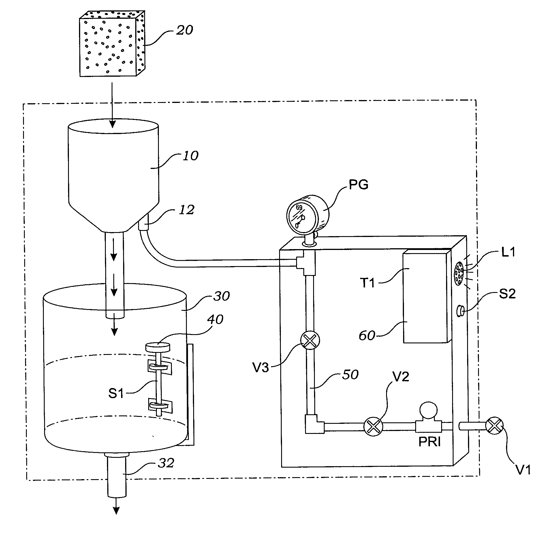
[0028] In a preferred embodiment of the present invention a dissolving tank 10 receives a solid chemical cake 20, as shown in FIG. 1, a mechanical schematic of the invention showing its several components and their relationship. A holding tank 30 is positioned below the dissolving tank 10 so that fluid may flow from tank 10 to tank 30 by gravity feed. The chemical cake 20 is able to dissolve when exposed to water forming a chemi...


PUM

PropertyMeasurementUnit
Flow rateaaaaaaaaaa
Levelaaaaaaaaaa

Abstract

A chemical solution dispensing apparatus uses a dissolving tank to hold a solid chemical cake. The dissolving tank delivers the chemical solution into a holding tank by gravitational flow and then to a receiving system. A liquid level sensor in the holding tank senses the liquid level of the solution and calls for water delivery through a conduit into the dissolving tank. When the level reaches a low point a circuit opens a inlet flow valve to deliver water into the dissolving tank. When the level reaches a high point, the circuit closes a safety shutoff valve in the conduit line. A pressure regulator and control relay enable the conduit line to be properly pressurized by an inlet source of water through a shutoff valve that is normally open. When the level in the holding tank rises above the high point, an alarm signal is released to initiate an audible alarm.

Description

BACKGROUND OF THE INVENTION RELATED APPLICATIONS [0001] This application claims priority of a prior filed provisional patent application, Ser. No. 60551746, filed on Mar. 10, 2004, which discloses the same invention as disclosed and claimed herein.FIELD OF THE INVENTION [0002] This invention relates generally to chemical water treatment and more particularly to a system by which a solid chemical cake may be dissolved and fed under controlled conditions for use in a downstream application. DESCRIPTION OF RELATED ART [0003] The following art defines the present state of the field of the present invention, and each disclosure is hereby incorporated herein by reference: [0004] Yao et al., U.S. 2004 / 0151062, discloses a novel interlocked automatic chemical mixing system and method of use which is particularly well-suited to preparing a final diluted HF (hydrofluoric acid) mixture of desired concentration for the post-cleaning rinsing of semiconductor wafer substrates. The automatic chemi...

Claims


Application Information

Patent Timeline
IPC IPC(8): B01F15/02
CPCB01F1/0022B01F15/00344B01F15/00155Y10T137/27B01F21/20B01F35/2112B01F35/2211
Inventor FLEIG, JOHN
Owner FLEIG JOHN
Why Eureka
Try Eureka