[0013]The present invention is directed to methods for
laser cutting a tubular workpiece which helps to reduce the number of post-cutting
processing steps by preventing oxidation and preventing recast from adhering to the workpiece material during the laser cutting process. The present invention prevents oxidation of the workpiece by utilizing a laser apparatus that utilizes an
inert gas, such as
argon or
helium, rather than air or
oxygen, to create the slots or kerfs which form the pattern
cut into the workpiece. The absence of
oxygen in the cutting process thus prevents the workpiece from being oxidized during laser cutting. The present invention also utilizes a disposable, sacrificial
mask which helps to prevent damage to the workpiece by covering the surface of the workpiece as it is being laser
cut. The present invention is particularly beneficial in manufacturing intricately shaped devices from a hollow workpiece, such as a stent.
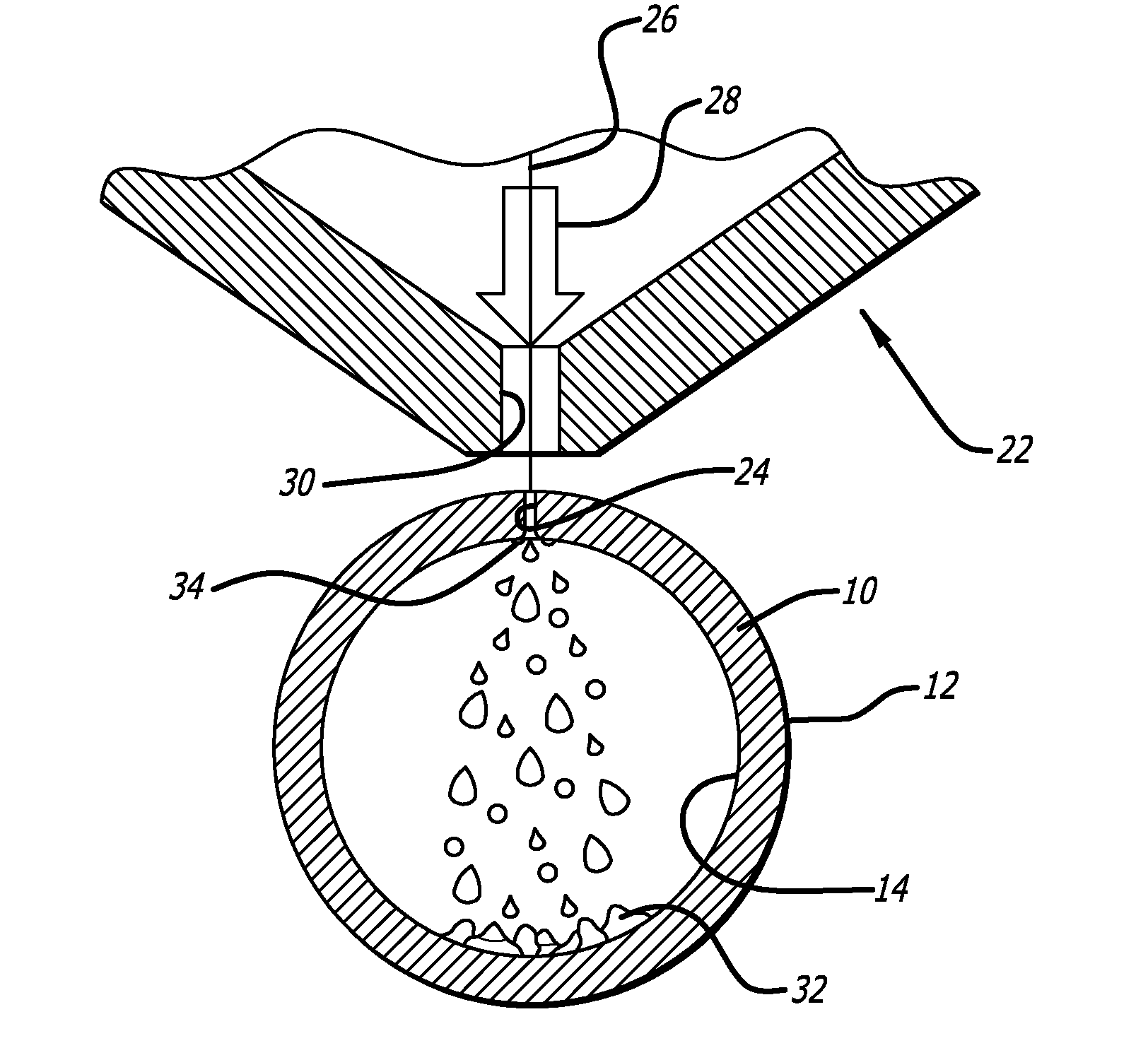
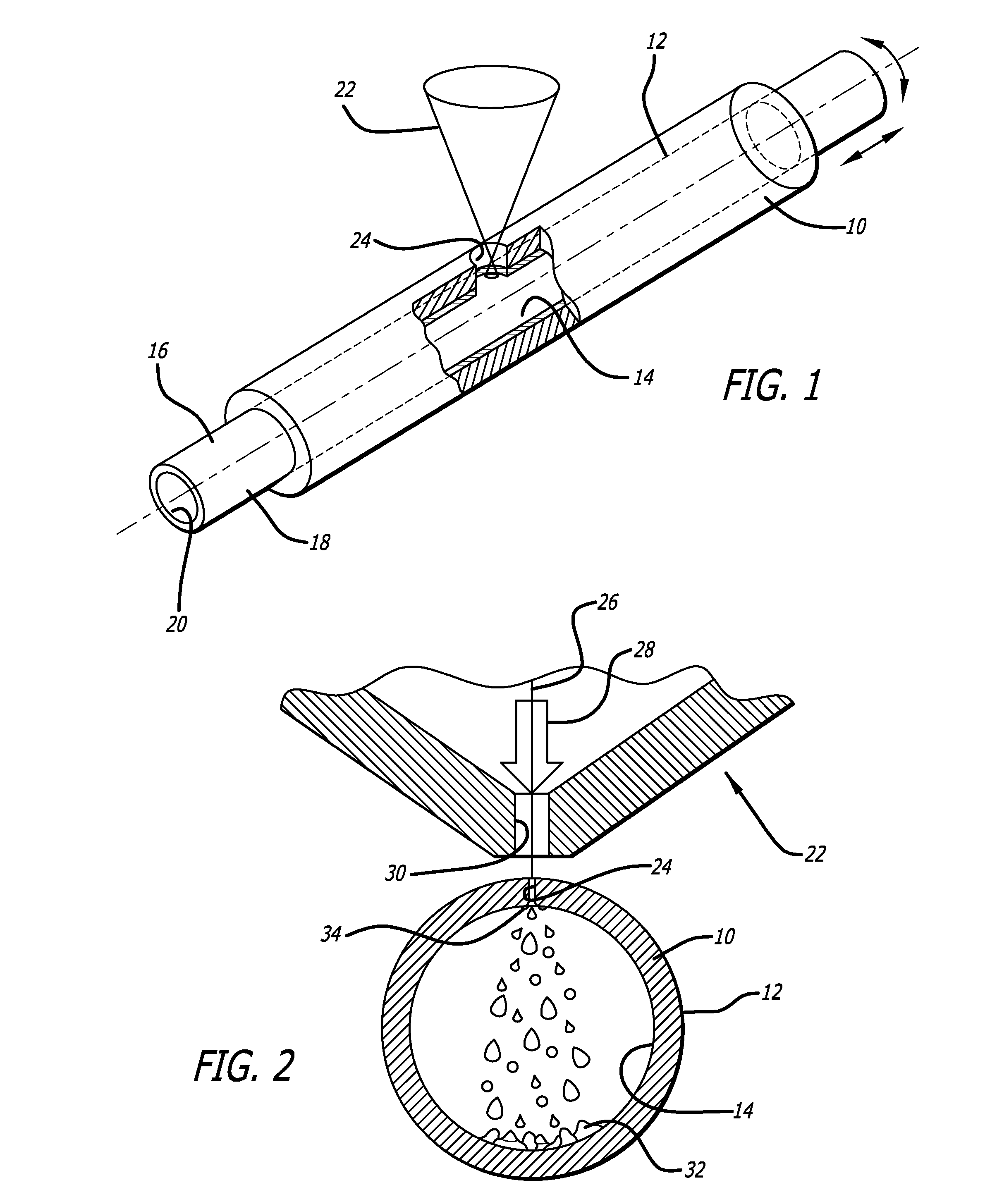
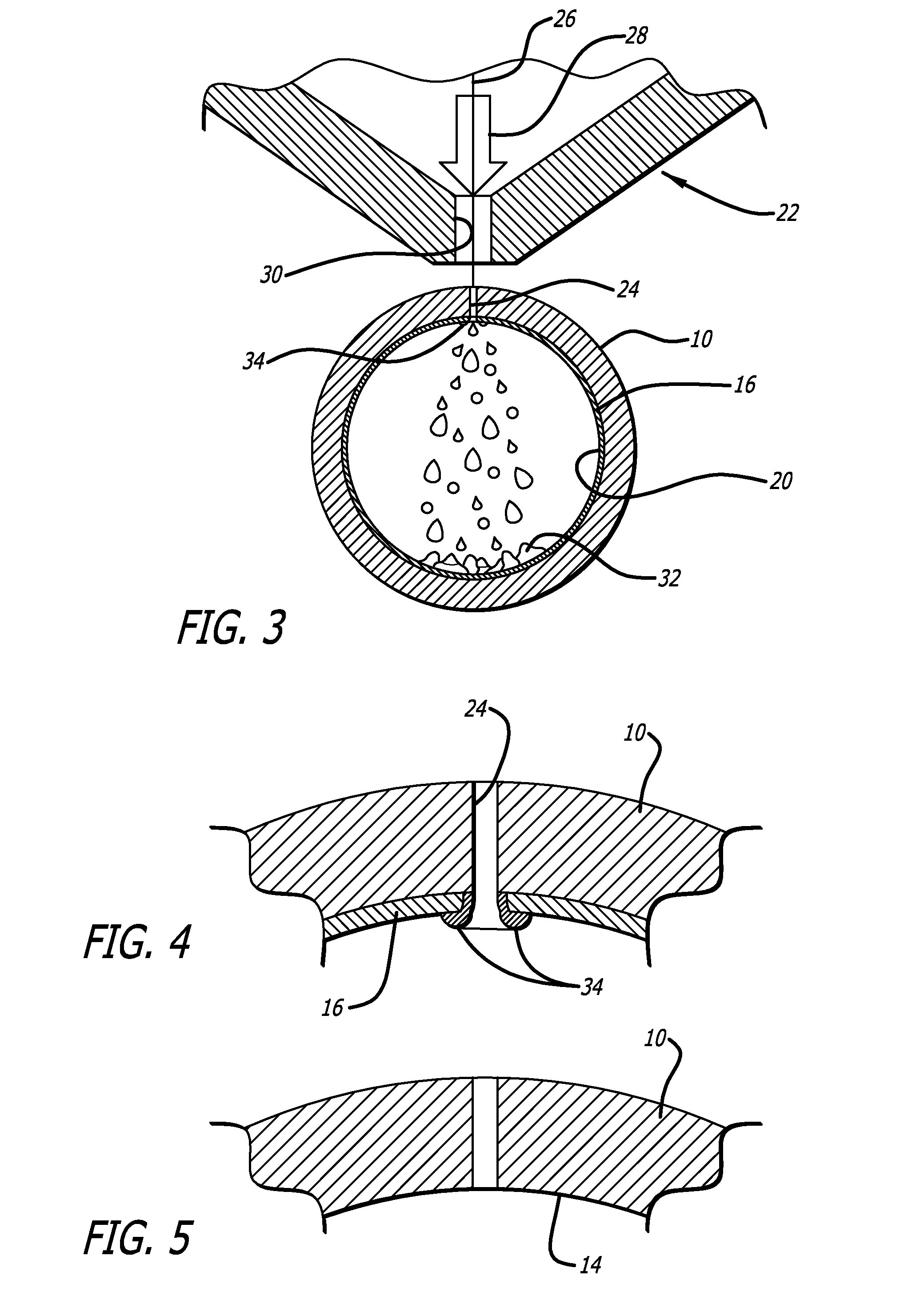
[0014]In one aspect of the invention, the disposable
mask can be placed over at least a portion of the inner surface of the tubular member or tubing which is being laser cut. In the laser cutting process, recast material formed during the cutting process is forced through the kerf via the pressurized
inert gas and is collected on the surface of the disposable
mask, rather than on the inner surface of the tubular member. Tubing made from Nitinol can be laser cut using an
inert gas without the risk of the recast material being welded onto the inner surface of the tubular member. During the cutting operation, both the tubular member and the disposable mask are simultaneously cut to the same pattern. During cutting, the expelled molten Nitinol collects on the inner surface of the disposable mask instead of directly on the inner surface of the tubular member, and afterward the expelled material and sacrificial mask can be removed because neither are strongly affixed to the inner surface of the Nitinol workpiece. Because the
inert gas prevents oxidation of the sidewalls of the tubular member, the present invention allows the cut workpiece to be further processed with little or no need to grit blast tough oxidized material from the stent wall prior to
electropolishing.
[0016]The present invention utilizes a variety of mechanical techniques to remove the sacrificial mask from the tubular member, along with a variety of chemical
removal techniques which can be coupled with the mechanical techniques to quickly and cleanly remove the
dross and sacrificial mask from the inner wall of the formed tubular member.
[0017]In one particular aspect of the present invention, the purely mechanical techniques for removing the
dross and sacrificial mask is to
attack the
dross only, utilizing equipment which will
grind, hone or bead-blast the dross only.
Dross also can be removed utilizing a tool such as a
wire brush or
reamer. Another way to clean the lased tubular member would be to mechanically
attack the sacrificial mask only. Similar mechanical techniques could be used to remove the sacrificial mask. Lastly, these same techniques could be used to mechanically
attack both the dross and sacrificial mask. These various techniques provide simple but useful manufacturing steps to separate the lased tubular member from the sacrificial mask and dross.
[0021]In another aspect of the present invention, the procedure for removing the sacrificial mask and dross from the lased tubular member would utilize a combination of chemical
removal techniques with mechanical
removal techniques, such as the ones addressed above. For example, after cutting, the lased tubular member and sacrificial mask can be subjected to a
chemical attack which would only attack the tubular member material therefore dissolving the dross. A
chemical solution would be applied to both the tubular member and sacrificial mask. The application of the
chemical solution is designed to primarily attack the tubular member, rather than the disposable mask material. As such, the chemicals are selected which preferably attack the material of the tubular member, leaving the sacrificial mask material generally unharmed. In one aspect of the invention, the chemical solution attacks the tubular member by
etching it. It should be noted that the recast material (especially the thin connection between the sidewall and recast
metal) has a very large
surface area to volume ratio and therefore it is much more readily attacked by the chemical solution than the body of the tubular member itself. This process of applying a chemical solution which primarily attacks the material forming the tubular member eliminates or weakens much of the recast material formed in the kerfs and elsewhere, thereby allowing the tubular member and the sacrificial mask material to be more easily separated.
[0028]The use of the
present method in forming a
medical device, such as a stent, eliminates the need for
grit blasting or otherwise chemically removing the oxidized cast material prior to electropolishing since air or oxygen is no longer used in the laser cutting process. The use of the
inert gas eliminates the possibility that the sidewalls of the tubular member and recast material will become oxidized during laser cutting. As a result, the
elimination of sidewall oxidation helps to prevent
cracking or fracturing of the stent during use and eliminates some of the subsequent
processing which would be otherwise be needed to remove the oxidized material from the tubular member. As a result, the formed workpiece can be sent for electropolishing without the need for additional processing which could break or irreparably damage the fragile struts which form the stent.

