Cutting Device And Tape Printing Apparatus Equipped Therewith

a cutting device and tape printing technology, which is applied in printing, metal working equipment, other printing equipment, etc., can solve the problems of tape-like members being damaged, tape printing equipment including cutting devices becoming larger in size, so as to ensure the return operation of the cutter blad

Inactive Publication Date: 2011-06-30
SEIKO EPSON CORP
View PDF9 Cites 5 Cited by
  • Summary
  • Abstract
  • Description
  • Claims
  • Application Information

AI Technical Summary

Benefits of technology

[0012]According to this kind of cutting device, by means of the cutter operation mechanism which causes the cutter unit to carry out the circulatory movement, the cutter unit moves in the width direction of the tape-like member, and carries out the cutting operation. Also, as the cutter operation mechanism can change the amount of cutting into the tape-like member by making the cutting start position different between the full cutting and half cutting using the same cutter unit in the cutting preparation operation, it is possible to carry out the full cutting and half cutting. Because of this, a need to configure the cutting device of separate devices, a full cutting device and a half cutting device, is eliminated. Consequently, by it being possible to share the full cutting device and half cutting device, it is possible to achieve a miniaturization of the cutting device.
[0013]Also, with the cutter operation mechanism, by making the withdrawal position different between the full cutting and half cutting, it is possible to prevent a problem of the tape-like member being damaged, or the like, due to a movement of the cutter unit in the return operation which is the operation after the withdrawal operation. Consequently, with the cutter mechanism, it is possible to safely carry out the return operation of the cutter unit.Application Example 2
[0015]According to this kind of cutting device, by the cutter operation mechanism causing the withdrawal position to move away from the tape surface of the tape-like member in the withdrawal operation at the half cutting time, it is possible to prevent a problem of the half-cut tape-like member being damaged, or the like, when the cutter blade carries out a movement in the return operation which is the operation after the withdrawal operation. Consequently, with the cutter operation mechanism, it is possible to safely carry out the return operation of the cutter blade.Application Example 3
[0017]According to this kind of cutting device, the cutter operation mechanism, including the first movement mechanism, second movement mechanism, and power transmission mechanism, causes the cutter unit to carry out the circulatory movement. By means of this kind of cutter operation mechanism, it is possible to cause the cutter unit to carry out the complex circulatory movement with a simple structure. Also, as the first movement mechanism and second movement mechanism come into conjunction by means of the power transmission mechanism, it is possible to cause accurate operations to be carried out in synchronization. Then, by the power transmission mechanism including the rotating circular plate and cam grooves, and causing the rotating circular plate to rotate by switching the rotation direction thereof between the forward direction and backward direction, carrying out the full cutting and half cutting, it is possible to realize the full cutting and half cutting by means of a simple configuration and an efficient method.
[0024]According to this kind of tape printing apparatus, as it includes the cutting device having the heretofore described advantages, it is possible to achieve a miniaturization, and in addition, it is possible to prevent a problem of the tape-like member being damaged due to a movement of the cutter unit, or the like. It is possible to realize a tape printing apparatus with which it is possible to safely carry out the return operation of the cutter blade without damaging the tape-like member, in particular, when the half cutting is carried out.

Problems solved by technology

However, with JP-A-2002-103281, as a cutting device is configured including a full cutting device, which carries out the full cutting, and a half cutting device, which carries out the half cutting, separately, there is a problem in that the cutting device becomes larger in size.
Along with this, there is a problem in that the tape printing apparatus including the cutting device also becomes larger in size.
Also, when the full cutting device and half cutting device are shared, there is a problem in that the tape-like member is damaged due to a movement for a return operation.
In particular, when the half cutting is carried out, there is a problem in that the half-cut tape-like member is damaged due to a movement of a cutter blade for the return operation thereof.

Method used


Image

  • Cutting Device And Tape Printing Apparatus Equipped Therewith
  • Cutting Device And Tape Printing Apparatus Equipped Therewith
  • Cutting Device And Tape Printing Apparatus Equipped Therewith

Examples


embodiment

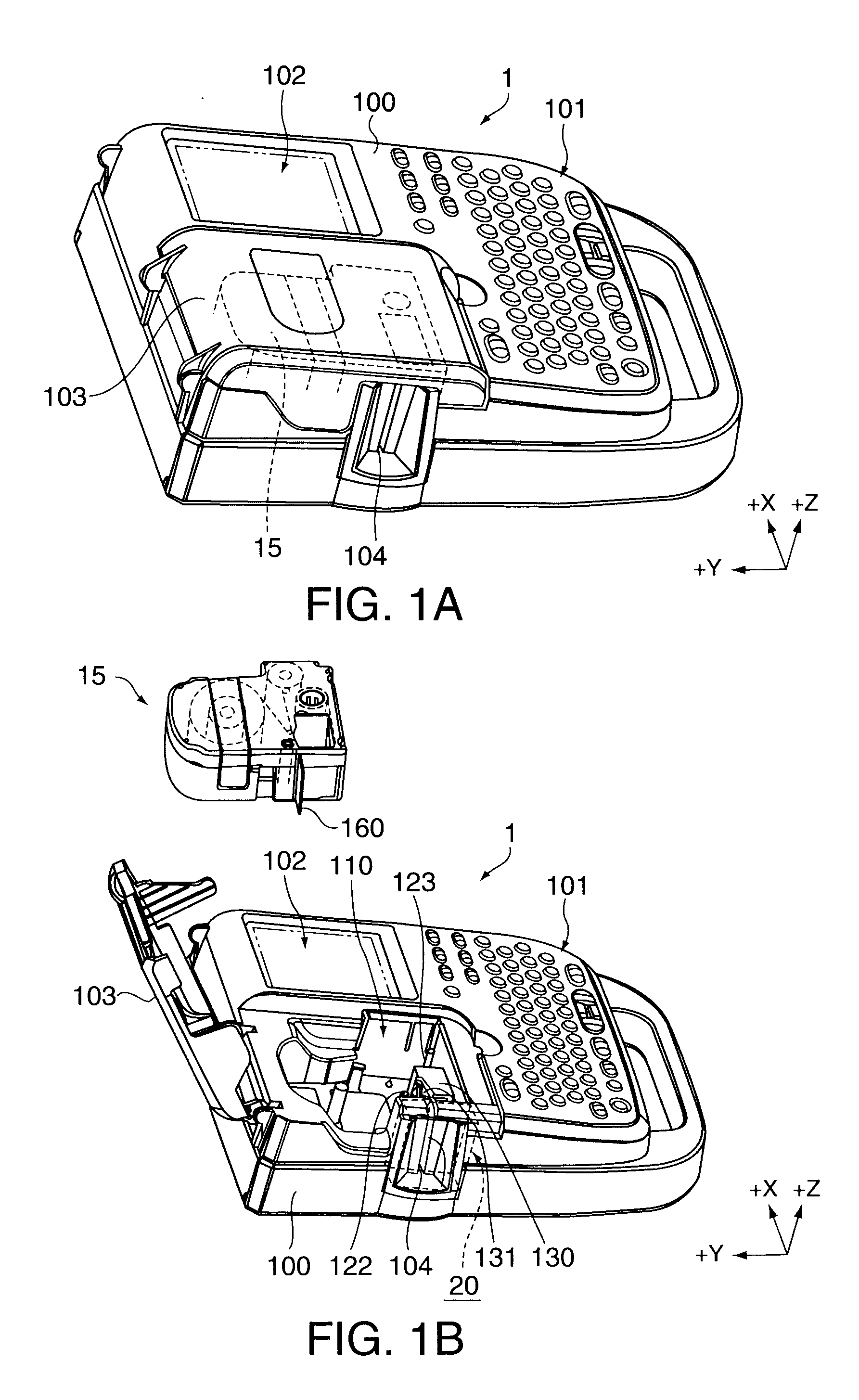
[0051]FIGS. 1A and 1B are perspective views of a tape printing apparatus, where FIG. 1A is a perspective view of the tape printing apparatus 1 in a condition in which an opening / closing cover 103 is closed, and FIG. 1B is a perspective view of the tape printing apparatus 1 in a condition in which the opening / closing cover 103 is opened. FIG. 1B shows a condition in which a tape cartridge 15 is removed from a mounting portion 110. With reference to FIGS. 1A and 1B, a description will be given of an external configuration of the tape printing apparatus 1.

[0052]In FIGS. 1A and 1B, a direction from an operating panel 101 of the tape printing apparatus 1 to the tape cartridge 15 (from the right to the left of the drawings) is taken to be a Y axis (+Y axis) direction, a direction from a tape discharge slit (ejection slot) 104 to the tape cartridge 15 (an upward direction from the bottom of the drawings) an X axis (+X axis) direction, and a direction perpendicular to the Y axis direction a...


PUM

PropertyMeasurementUnit
widthaaaaaaaaaa
Structuresaaaaaaaaaa
sizeaaaaaaaaaa

Abstract

A cutting device includes: a cutter unit having a cutter blade; and a cutter operation mechanism which causes the cutter unit to carry out a circulatory movement including a cutting preparation operation which causes the cutter unit to advance toward a tape-like member from a cutting start position, a cutting operation which causes the cutter unit to move to a cutting completion position, a withdrawal operation which causes the cutter unit to retreat from the cutting completion position to a withdrawal position, and a return operation which causes the cutter unit to return to a cutting stand-by position, wherein the cutter operation mechanism, in the return operation, makes the cutting start position and withdrawal position of the cutter unit different between a full cutting which cuts all of the tape-like member and a half cutting which cuts one portion of the tape-like member.

Description

[0001]The entire disclosure of Japanese Patent Application No. 2009-291942, filed on Dec. 24, 2009, is expressly incorporated by reference herein.BACKGROUND[0002]1. Technical Field[0003]The present invention relates to a cutting device and a tape printing apparatus equipped therewith.[0004]2. Related Art[0005]Heretofore, a tape printing apparatus has been known which carries out a printing on, while feeding, a tape-like member wherein a printing tape (coated with an adhesive) and release paper are stacked, and when the printing is finished, cuts off a portion on which the printing is done, making a label. The label made is used by stripping the printing tape from the release paper, and affixing it to a desired affixing surface. Also, the cutting has a full cutting, which cuts both the printing tape and release paper of the tape-like member by means of a full cutter, and a half cutting which cuts either the printing tape or release paper by means of a half cutter. By carrying out the...

Claims


Application Information

Patent Timeline
Patent Type & Authority Applications(United States)
IPC IPC(8): B41J11/66B26D5/08
CPCB26D1/045B26D1/455B41J11/703B41J11/666B26D5/08Y10T83/0333Y10T83/0581Y10T83/8748Y10T83/0348Y10T83/02
Inventor KOSUGE, SHINSAKU
Owner SEIKO EPSON CORP
Why Eureka
Try Eureka