Solid state positive force touch sensing

a positive force, solid state technology, applied in the field of control, can solve the problems of difficulty and cost to achieve with mechanical alternatives, unintended actuation risk, and the risk of not detecting an actuation at all

Inactive Publication Date: 2011-07-07
UICO
View PDF29 Cites 5 Cited by
  • Summary
  • Abstract
  • Description
  • Claims
  • Application Information

AI Technical Summary

Benefits of technology

[0011]Embodiments of the invention include; 1) solid-state touch-sensing technology; and 2) a developed surface over the sensing technology that serves to inhibit the sensing of unintended contact and enable a more definite determination of intended contact. These two elements combined together offer the benefit of implementing solid-state touch-sensing technology in products that lend themselves for a user to rest a finger on the discrete touch pads prior to an affirmative touch without triggering a sensed event.

Problems solved by technology

This is very difficult and costly to achieve with mechanical alternatives.
If the sensitivity is set too high, there is risk of unintended actuation, as the touch pad may detect an actuation before the user's finger comes in contact with the touch pad, thereby acting like a proximity sensor.
If the sensitivity is set too low, there is risk of not detecting an actuation at all.
Hence, a significant drawback for this type of technology is its inability to distinguish between an affirmative touch and an unintended touch.
This limitation is further exaggerated in products such as handheld products that use QWERTY keyboards.
The resting the user's fingers on the discrete touch pad prior to an affirmative touch almost always results in unintended touch actuations.

Method used


Image

  • Solid state positive force touch sensing
  • Solid state positive force touch sensing
  • Solid state positive force touch sensing

Examples


Embodiment Construction

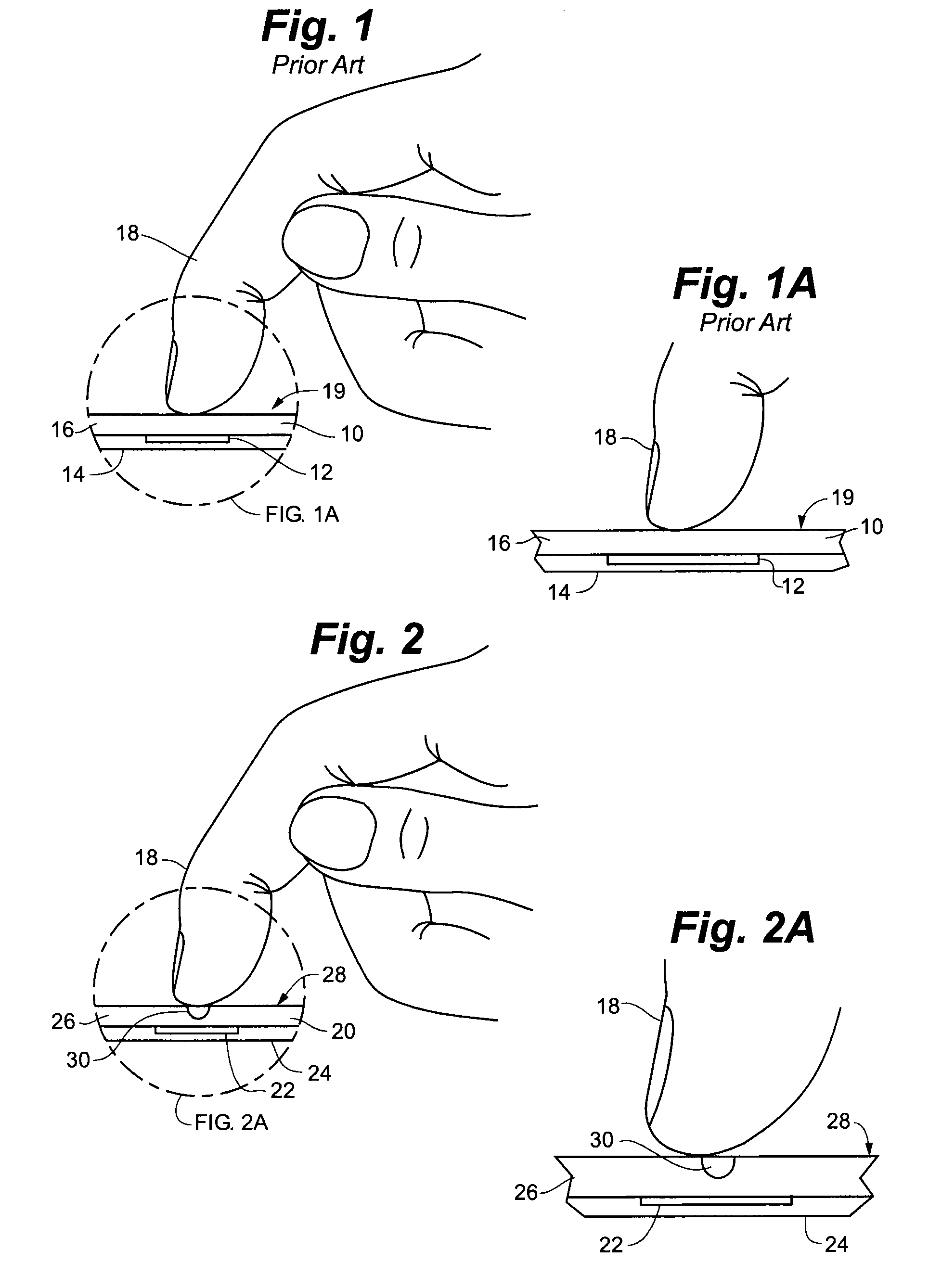
[0032]FIG. 1 depicts a prior art capacitive touch sensor pad 10. Capacitive touch pad 10 generally includes capacitive touch sensor 12 which may be mounted on PC board 14 and overlain with a layer of insulative protective material 16. In this example embodiment, when finger 18, other body part or touching member of a user is placed in sufficient proximity with sensor 12, a capacitive signal is generated by sensor 12 to indicate a control actuation. A drawback of this prior art system is that it is difficult or impossible to adjust the sensitivity of the system to enable a user to place a finger on pad surface 19, as may be sometimes desirable to, for example, permit “touch typing” operation, without causing actuation. Thus, in the prior art resting the fingers on insulative protective material 16 overlying capacitive touch sensor 12 nearly always results in an unintended control actuation.

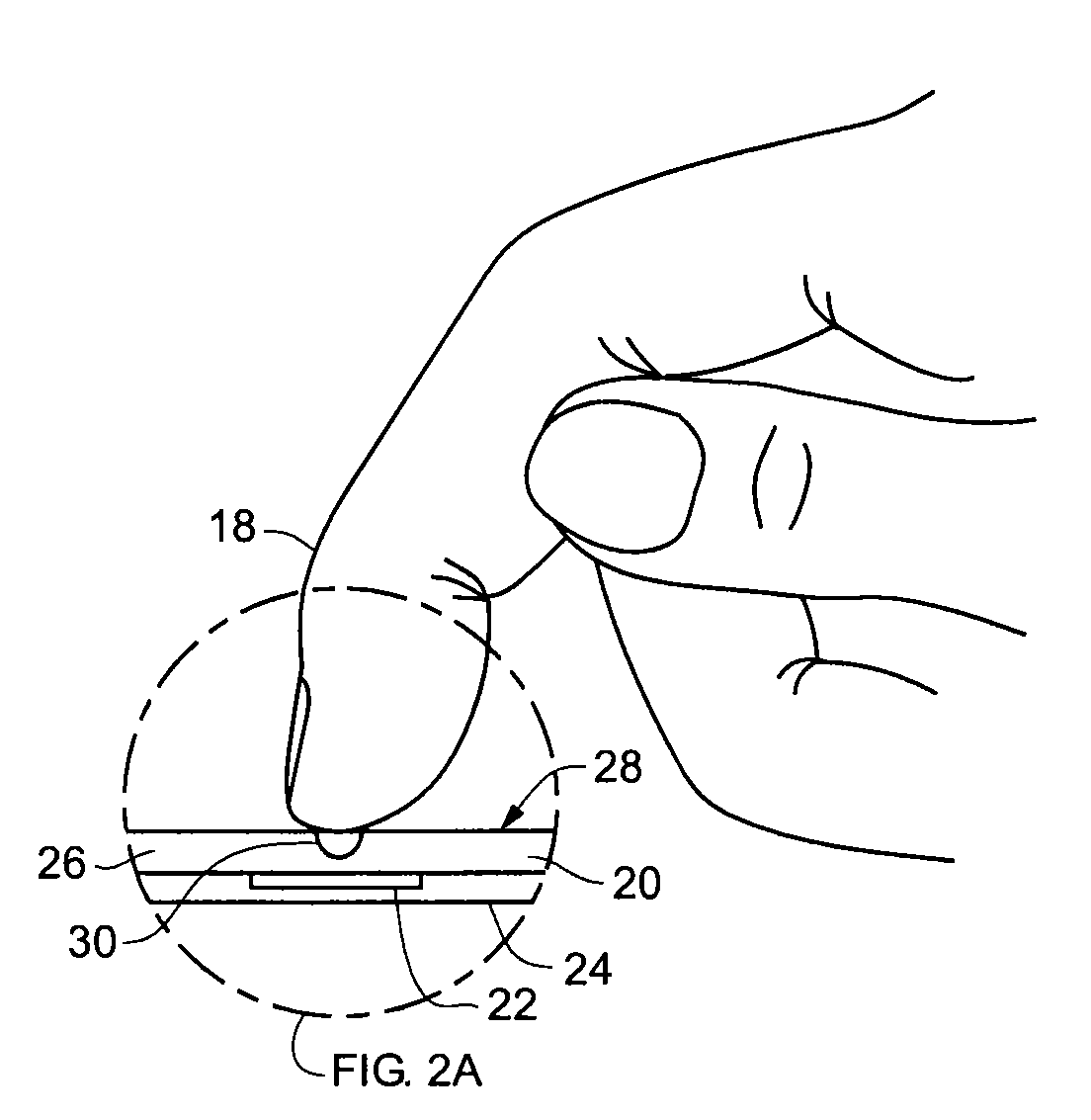
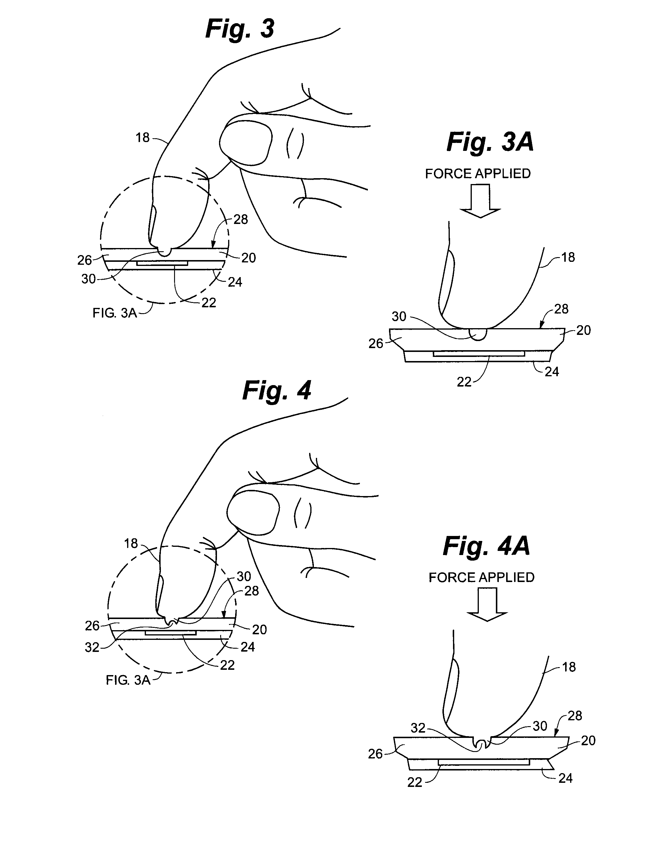
[0033]FIGS. 2 and 3 depict touch sensor pad 20 according to an example embodiment of the invent...


PUM


Abstract

A touch sensor pad, including a touch sensor that senses the presence of a touching member placed proximate the touch sensor. A layer of protective material overlies the touch sensor. The layer of protective material has a first surface proximate the touch sensor and an opposing second surface distal from the touch sensor. The second surface includes a resting surface portion and a developed surface portion. The developed surface portion is recessed below the resting surface portion such that the developed surface portion is nearer to the touch sensor than the resting surface portion. The touch sensor has a sensitivity such that the presence of a touching member in contact with the resting surface portion does not result in an actuation of the touch sensor while the presence of a touching member pressed into the developed surface portion does result in the actuation of the touch sensor.

Description

CLAIM TO PRIORITY[0001]This application claims the benefit of U.S. Provisional Patent Application No. 61 / 258,378, the entire contents of which is incorporated herein by reference.FIELD OF THE INVENTION[0002]The present invention relates to controls, and more specifically to solid-state touch activated control pads.BACKGROUND OF THE INVENTION[0003]Touch screens are electronic visual displays that can detect the presence and location of a touch on the surface of the display area. Touching of the display is generally done with a finger or hand. Touch screens operate under a variety of electronic, acoustic or optical principals. Solid-state touch-sensing technologies, like discrete touch pads and multi-touch touch screens have been successfully implemented in a wide variety of products, ranging from cell phones to large display monitors. The success of these technologies in recent years is a direct result of the benefits that these technologies bring to products in which they are used.[...

Claims


Application Information

Patent Timeline
Patent Type & Authority Applications(United States)
IPC IPC(8): G06F3/041
CPCG06F3/044G06F3/016G06F3/0444
Inventor WADIA, BAHAR N.
Owner UICO
Why Eureka
Try Eureka