Wood-type golf club head with adjustable sole contour

Active Publication Date: 2011-07-07
CALLAWAY GOLF CO
View PDF100 Cites 9 Cited by
  • Summary
  • Abstract
  • Description
  • Claims
  • Application Information

AI Technical Summary

Benefits of technology

[0017]The present invention seeks to overcome the variability and uncertainty of the face angle at address (natural sole) for a wood having a single keel area (line or point)

Problems solved by technology

The measured face angle generally is not perceived by the golfer because it

Method used


Image

  • Wood-type golf club head with adjustable sole contour
  • Wood-type golf club head with adjustable sole contour
  • Wood-type golf club head with adjustable sole contour

Examples


embodiment 1

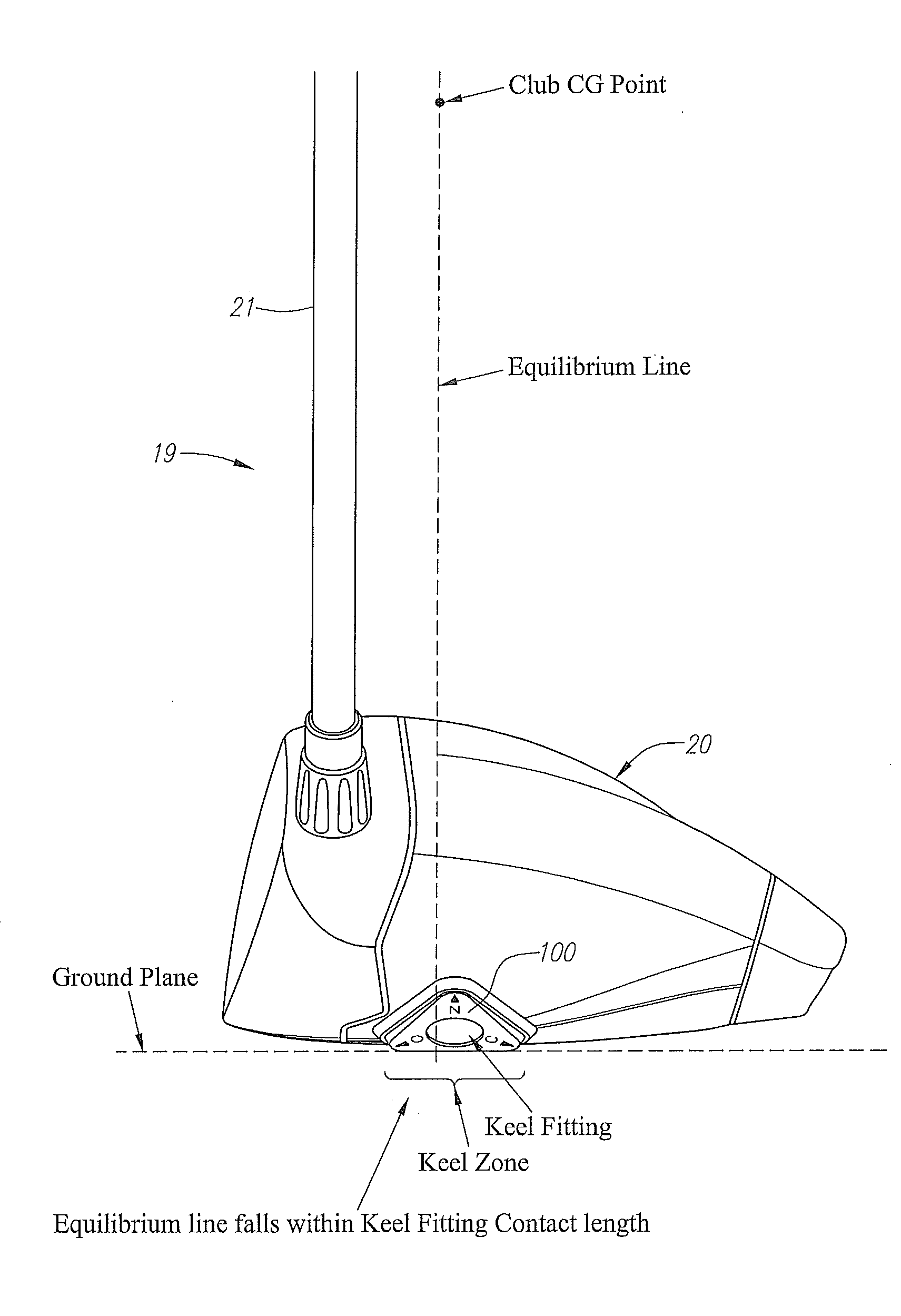
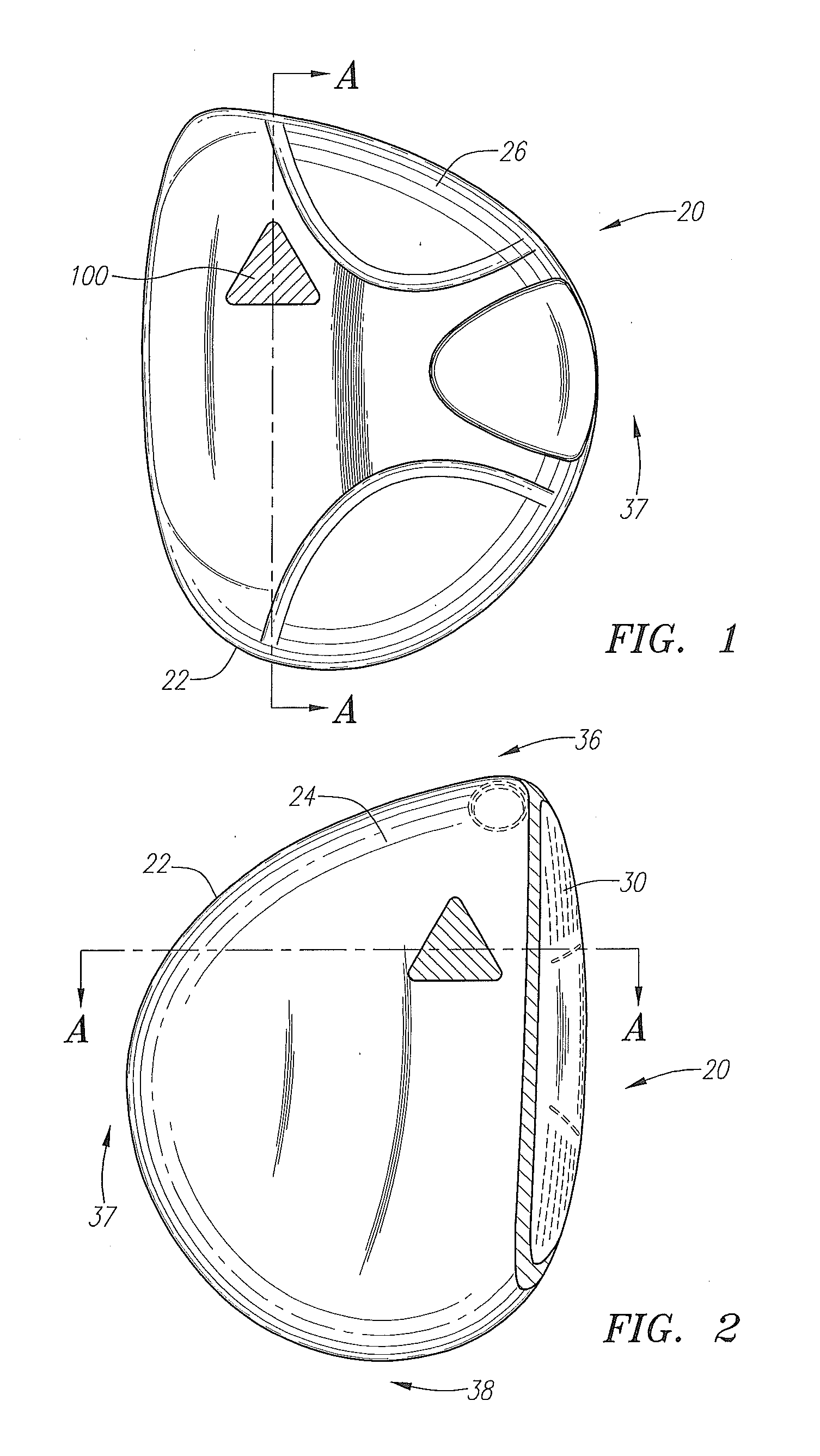
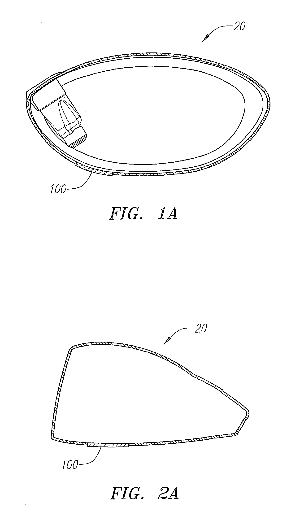
[0086]As shown in FIGS. 1-7, a golf club head 20 has an adjustable keel zone member 100. The adjustable keel zone member 100 is positioned on a sole 26 of the golf club head 20. The golf club head 20 also preferably has a body 22 with a crown 24, a front wall 30 and the sole 26. The golf club head 20 also has a heel end 36, an aft end 37 and a toe end 38.

[0087]The golf club head 20 is preferably a multiple material golf club head such as disclosed in Foster et al., U.S. patent application Ser. No. 12 / 240,425, filed on Sep. 29, 2008, for a Golf Club Head, which is hereby incorporated by reference in its entirety. Alternatively, the golf club head 20 is a club head such as disclosed in Murphy et al., U.S. Pat. No. 7,383,577 for a Multiple Material Golf Club Head, which is hereby incorporated by reference. Alternatively, the golf club head 20 is a club head such as disclosed in Williams et al., U.S. Pat. No. 7,390,269 for a Golf Club Head, which is hereby incorporated by reference. Alt...

embodiment 2

[0106]An alternative embodiment is shown in FIGS. 26-32. A golf club head 42 is generally designated. In a preferred embodiment, the club head 42 is generally composed of three components, a face component 60, a mid-body 61, and an aft-weight component 65. The mid-body 61 preferably has a crown section 62 and a sole section 64. The mid-body 61 optionally has a ribbon section 90.

[0107]The golf club head 42, when designed as a driver, preferably has a volume from 200 cubic centimeters to 600 cubic centimeters, more preferably from 300 cubic centimeters to 500 cubic centimeters, and most preferably from 420 cubic centimeters to 470 cubic centimeters, with a most preferred volume of 460 cubic centimeters. The volume of the golf club head 42 will also vary between fairway woods (preferably ranging from 3-woods to eleven woods) with smaller volumes than drivers.

[0108]The golf club head 42, when designed as a driver, preferably has a mass no more than 215 grams, and most preferably a mass ...

embodiment 3

[0131]Yet another embodiment of the present invention, which comprises two contact points between a sole or bottom surface of the golf club and the ground, is disclosed in FIGS. 33A, 33B, 34A, 34B, 35A-C, and 36A-C. As shown in FIGS. 33A, 33B, 35A-C and 36A-C, a golf club head 200 has a body 220 with a front wall 230, a crown 240, a sole 260, a heel end 270, an aft end 280, and a toe end 290. The golf club head 200 further has an adjustable fitting member 300 positioned within a recessed area 310 in the sole 260 towards the aft end 280 of the golf club head 200. The recessed area 310 preferably is closer to the heel end 270 of the golf club head 200 than the toe end 290.

[0132]The fitting member 300 preferably is secured to the sole 260 of the golf club head 200 with a bolt 320 that passes through a bore 301 in the fitting member 300 and engages a threaded bore 315 in the recessed area 310 of the sole 260. An alternative embodiment of this design may dispense with the recessed area 3...


PUM


Abstract

A golf club comprising an adjustable fitting member semi-permanently attached rearwardly on a sole is disclosed herein. The fitting member can be rotated to adjust the measured and perceived face angle of the golf club head at address without changing the relative relationship of the club with respect to the shaft, which would alter the lie and loft of the golf club head.

Description

CROSS REFERENCES TO RELATED APPLICATIONS[0001]The Present Application is a continuation-in-part of U.S. patent application Ser. No. 12 / 467,891, filed on May 18, 2009.STATEMENT REGARDING FEDERALLY SPONSORED RESEARCH OR DEVELOPMENT[0002]Not ApplicableBACKGROUND OF THE INVENTION[0003]1. Field of the Invention[0004]The present invention relates to a golf club head. More specifically, the present invention relates to a wood-type golf club head with an adjustable sole contour.[0005]2. Description of the Related Art[0006]The prior art discloses golf clubs with means for adjusting the face angle. The face angle of a golf club is defined as the angle of the face to the grounded sole line with the shaft hole perpendicular to the line of flight. Maltby, Golf Club Design, Fitting, Alteration, &Repair, The Principles &Procedures, 4th Edition, Ralph Maltby Enterprises, (1995).[0007]The perceived face angle is different than the measured face angle as would be measured on a device such as a CMM or...

Claims


Application Information

Patent Timeline
IPC IPC(8): A63B53/06A63B53/00A63B53/04
CPCA63B53/0466A63B53/06A63B2053/0408A63B2053/0412A63B2053/0416A63B2053/0437A63B2053/0458A63B2053/0491A63B2209/00A63B2209/023A63B2053/0433A63B60/00A63B53/0412A63B53/0437A63B53/0458A63B53/0408A63B53/0416A63B53/0433
Inventor CACKETT, MATTHEW T.EVANS, D. CLAYTONHOCKNELL, ALAN
Owner CALLAWAY GOLF CO
Why Eureka
Try Eureka