Apparatus for Controlling Channel Power Level in a Multi Channel System

a multi-channel system and power level technology, applied in the direction of electrical apparatus, multiplex communication, electromagnetic transmission, etc., can solve the problems of channel power level not being the same, channel over attenuation, channel power level variability, etc., to overcome the variability in the output optical power of each transmitter and the flatness and dispersion of components in the network, and reduce insertion loss

Inactive Publication Date: 2008-04-24
GENERAL INSTR CORP
View PDF8 Cites 19 Cited by
  • Summary
  • Abstract
  • Description
  • Claims
  • Application Information

AI Technical Summary

Benefits of technology

[0027]Those of skill in the art will appreciate that the present invention allows an operator to individually control the power level of each communication channel in a network without causing degradation to any other electrical or optical parameters of the transmitter. This invention will overcome the variability in the output optical power of each transmitter and the flatness and dispersion of components in the network. An operator may also equalize the power levels of all of the channels received by a user to the same level. This leveling allows an operator to guarantee that all the channels are arriving to the receiver at the same optical level. Further, since the variable optical attenuator is mounted internally to optical transmitter it will be protected from environmental factors by the casing of the optical transmitter. The variable optical attenuator also does not require extra installation space that an external optical modulator would require. The variable optical attenuator can also be properly configured at the time of manufacture of a transmitter which avoids selection of less than an optimally compatible attenuator with a laser by a technician and provides for reduced insertion loss, such as due to reflection, often associated with an external attenuator.

Problems solved by technology

The extensive and complex networks are often difficult for a cable operator to manage and monitor.
However, this approach also has significant impact on other communication parameters of the optical signals such as the carrier to noise ratio (C / N) and distortion levels, such as Composite Second Order & Composite Triple-Beat (i.e. CSO and CTB).
This often results in some channels being over attenuated and the channel power levels not being the same.
Typical optical attenuators are also very expensive, bulky and not always compatible with a transmission laser implementation.
Operators often have little precious space to devote to attenuators and technicians often match a less than optimal attenuator with a laser transmitter unit, often resulting in excessive insertion loss, such as due to reflection, often associated with an external attenuator.

Method used


Image

  • Apparatus for Controlling Channel Power Level in a Multi Channel System
  • Apparatus for Controlling Channel Power Level in a Multi Channel System
  • Apparatus for Controlling Channel Power Level in a Multi Channel System

Examples


Embodiment Construction

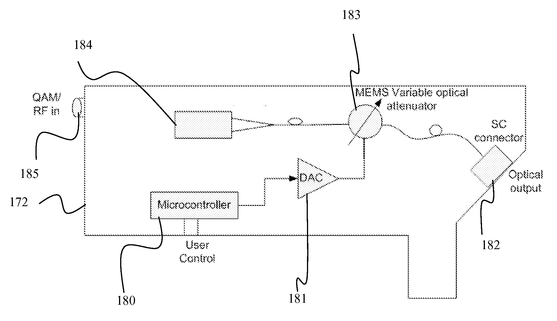
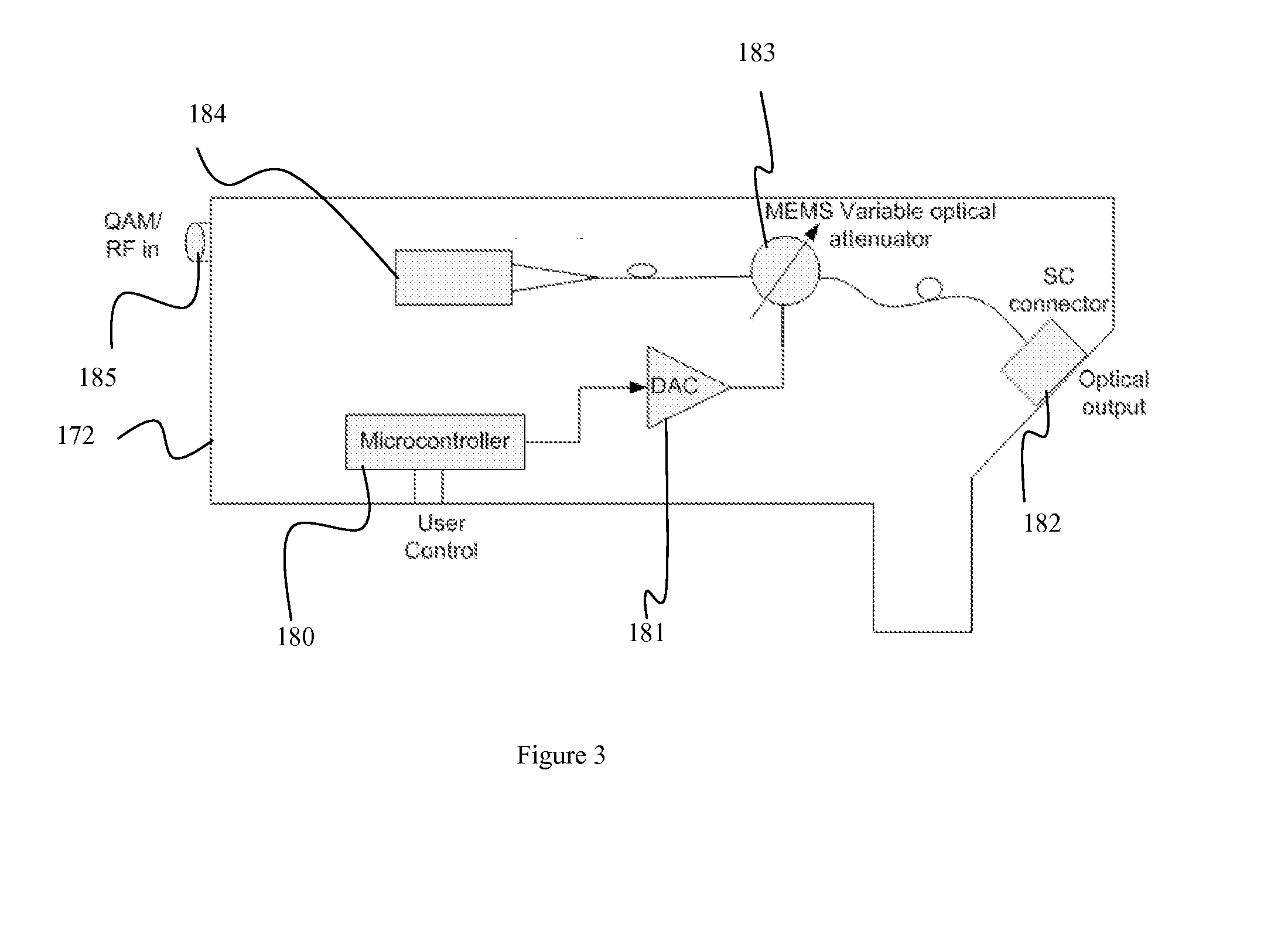
[0033]The present invention allows an operator to individually control the power level of each communication channel in a network, such as dense wavelength division multiplexed (DWDM) channels, which is an optical technology used to increase bandwidth over existing fiber optics backbones by sending multi channel signals which may have a channel separation of about 0.8 nm, or coarse wave division multiplexed (CWDM) channels, which may have a channel separation of about 20 nm, without affecting other parameters of the channels. For example, the operator preferably may individually control the power level of channels in a directed and / or external modulated CATV 1550 nm transmitter with a system which has user capability to adjust the output optical power of each transmitter to his desired level of output optical power without causing degradation to any other electrical or optical parameters of the transmitter. This invention allows an operator to overcome the variability in the output ...


PUM


Abstract

The present invention allows an operator to individually control the power level of each communication channel in a network without affecting other parameters of the channels. Each optical transmitter contains a voltage controlled variable optical attenuator which is controlled by a microcontroller to attenuate the optical communication signal to a desired level. The operator can adjust each transmitter separately to overcome the variability in the output optical power of each transmitter, the flatness of the WDM component, EDFA flatness, dispersion of the fiber, etc.

Description

FIELD OF THE INVENTION[0001]The present invention relates to adjusting the power level of a communication channel. More particularly, the present invention relates to adjusting the power level of an individual communication channel in a network.BACKGROUND OF INVENTION[0002]Coaxial cable television systems have been in widespread use for many years and extensive networks have been developed. The extensive and complex networks are often difficult for a cable operator to manage and monitor. A typical cable network generally contains a headend which is usually connected to several nodes which provide content to a cable modem termination system (CMTS) containing several receivers, each receiver connects to several modems of many subscribers, e.g., a single receiver may be connected to hundreds of modems. In many instances several nodes may serve a particular area of a town or city.[0003]The hybrid fiber coaxial (HFC) network and CATV market is driving toward highest density transport whe...

Claims


Application Information

Patent Timeline
Patent Type & Authority Applications(United States)
IPC IPC(8): H04B10/04
CPCH04B10/07955H04B10/564H04J14/0221H04J14/025H04J14/0282H04J14/0298H04J14/0246H04J14/0226
Inventor KHALOUF, IHAB E.MIGUELEZ, PHILIP
Owner GENERAL INSTR CORP
Why Eureka
Try Eureka