Anti-vibration suitcase wheel and suitcase using the same

a suitcase wheel and anti-vibration technology, applied in the field of suitcases, can solve problems such as uneasy user feeling, and achieve the effect of absorbing shock more effectively

Inactive Publication Date: 2011-07-14
JIANG HANHUI
View PDF9 Cites 15 Cited by
  • Summary
  • Abstract
  • Description
  • Claims
  • Application Information

AI Technical Summary

Benefits of technology

The cooperation between the limit slot and the buffe

Problems solved by technology

As a result, such a suitcase has no anti-vibratio

Method used


Image

  • Anti-vibration suitcase wheel and suitcase using the same
  • Anti-vibration suitcase wheel and suitcase using the same
  • Anti-vibration suitcase wheel and suitcase using the same

Examples


Embodiment Construction

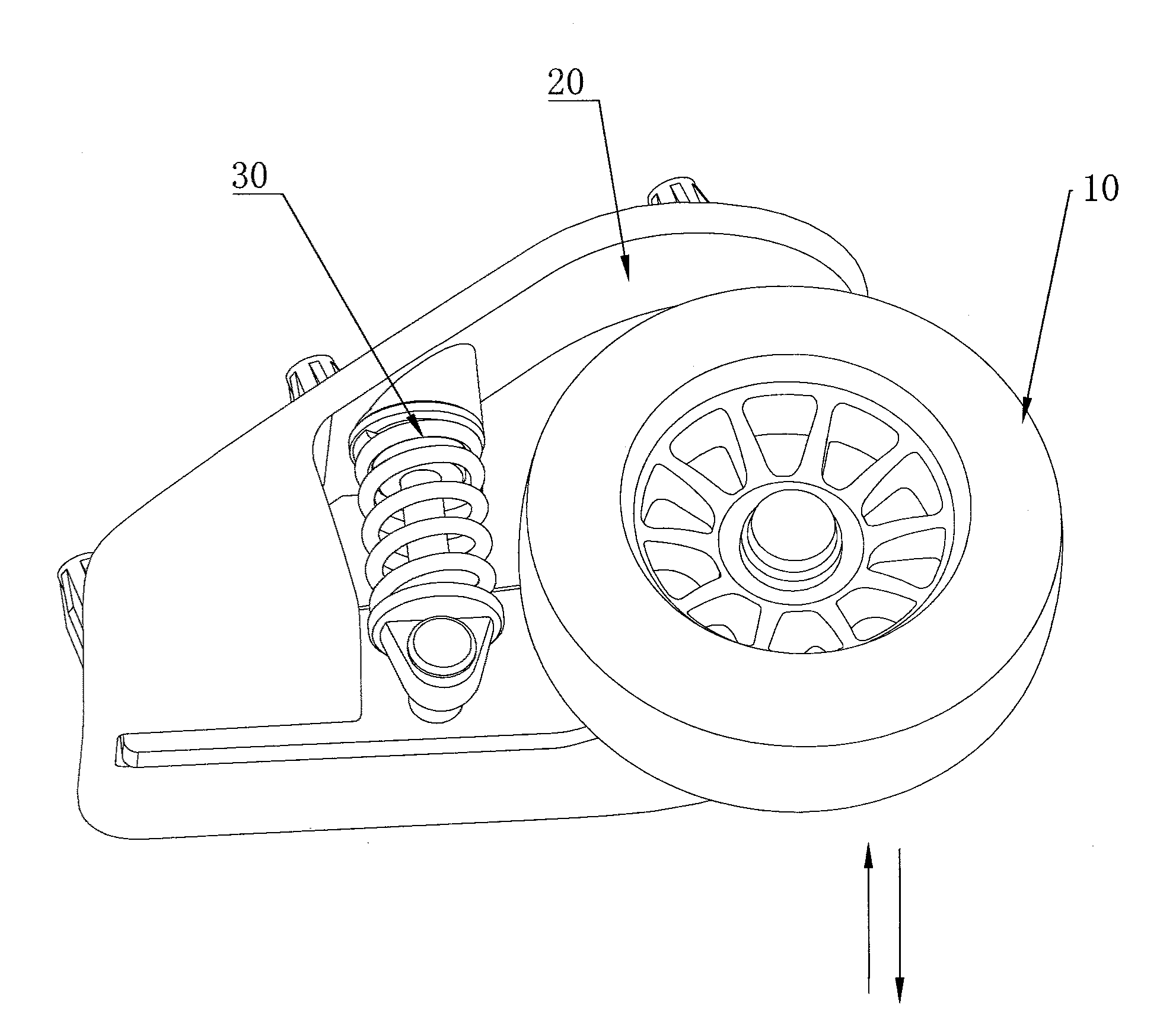
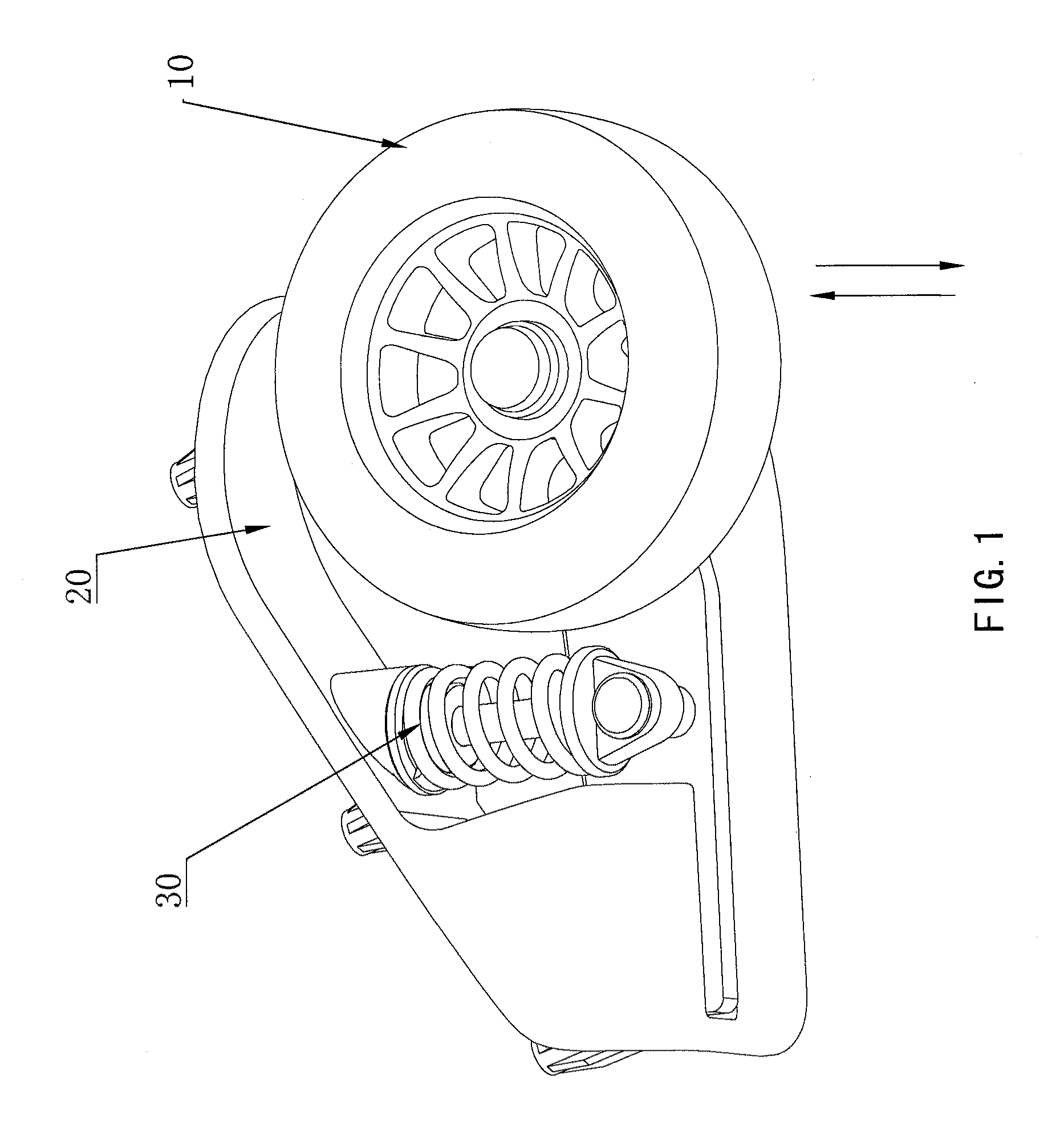
FIG. 1 shows an anti-vibration suitcase wheel according to an embodiment of the present invention. The anti-vibration suitcase wheel comprises a wheel body 10, a wheel seat 20, and a buffering assembly 30 for lessening the shock of an impact to the wheel body 10 and connected between the wheel body 10 and the wheel seat 20.

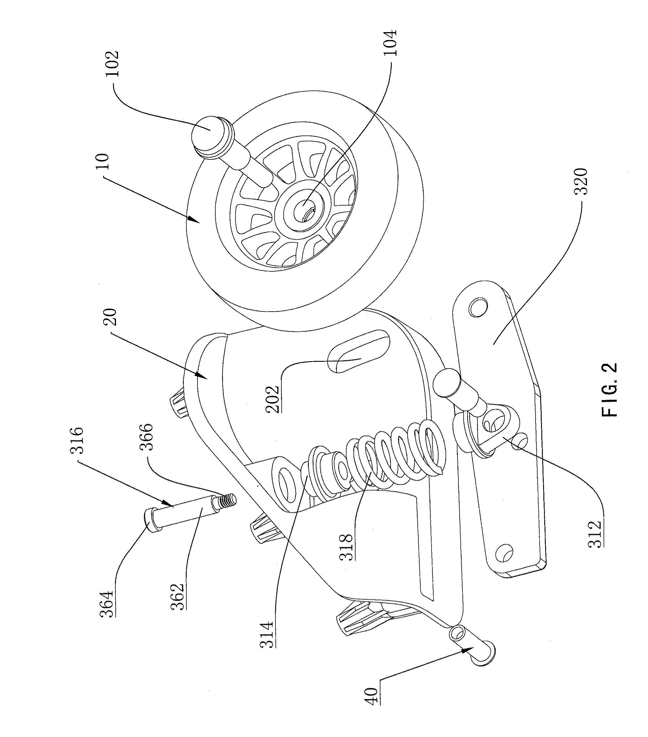
As FIG. 2 shows, a limit slot 202 extending along the direction of buffering is provided on the wheel seat 20, the wheel body 10 is hinged to the shaft 102, and the shaft 102 is inserted into and matched with the limit slot 202 and movable along the direction of buffering in the limit slot 202. The above mentioned direction of buffering is the force direction that the wheel body 10 being shocked.

The buffering assembly 30 comprises an elastic assembly and a vibration-transmitting lever 320, the vibration-transmitting lever 320 is pivoted to the wheel seat 20 via a pin 40 at one end and is hinged to the shaft 102 at the other end, the elastic assembly is connected w...


PUM


Abstract

An anti-vibration suitcase wheel which has a wheel body, a shaft as well as a wheel seat. A buffer assembly lessens the shock of any impact to the wheel body where the buffer assembly is connected between the wheel body and the wheel seat. The wheel body is hinged to the shaft and the shaft is inserted into and matched with a limit slot extending along a direction of buffering.

Description

BACKGROUND OF THE INVENTIONThe present invention relates to a suitcase. More particularly, the present invention relates to an anti-vibration suitcase wheel to reduce the suitcase vibration, and a suitcase using the wheel.A suitcase generally has wheels and a pull-rod, which are set at the two opposite ends of the suitcase. When the suitcase is used for transportation, the pull-rod is pulled out from one end of the suitcase, and the wheels for rolling set at the other end land on the ground. Traditionally, the wheels are directly joined to the wheel seat through axle, that is to say, the joint is a rigid connection. As a result, such a suitcase has no anti-vibration function, leading to uneasy feeling of the user.SUMMARY OF THE INVENTIONHaving outlined the state of the prior art and its attendant shortcomings, it is an object of the present invention is to provide an anti-vibration suitcase wheel that has anti-vibration function, and also to provide a suitcase using such wheels.The ...

Claims


Application Information

Patent Timeline
IPC IPC(8): A45C5/14B60G9/02B62B5/00
CPCA45C2005/148A45C5/14
Inventor JIANG, HANHUI
Owner JIANG HANHUI
Why Eureka
Try Eureka