

2-phase threshold detector based circuits
a detector based circuit and detector technology, applied in the direction of dc-dc conversion, power conversion systems, instruments, etc., can solve the problems of 133 mv output overshoot, variation of overshoot, and inaccuracy of threshold detector based circuits, so as to reduce the coarse phase overshoot
- Summary
- Abstract
- Description
- Claims
- Application Information
AI Technical Summary
Benefits of technology
Problems solved by technology
Method used
Image


Examples
first embodiment
The power consumption of the 2-phase threshold detector based circuit is dominated by the threshold detector speed and noise requirements in the fine phase. The power consumption in the transconductor 40 is generally negligible compared with that in the threshold detector. Therefore, the transconductor 40 adds very little penalty in power consumption compared with prior art threshold detector based circuits where constant charging currents are used. In computer simulations, the present invention has shown to reduce the overshoot and the input referred offset by a large factor without compromising the speed of operation. Therefore, much higher accuracy is achievable with the variable current charging method of the present invention.
The accuracy of the 2-phase circuit is determined by the variation in the fine phase overshoot. The smaller the fine phase overshoot, the better the accuracy becomes. The constant overshoot at the end of the fine phase manifests itself as a constant input ...
second embodiment
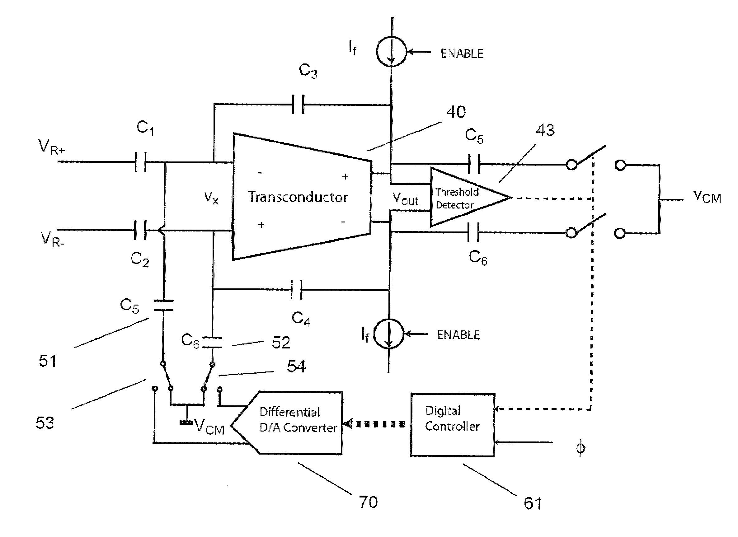
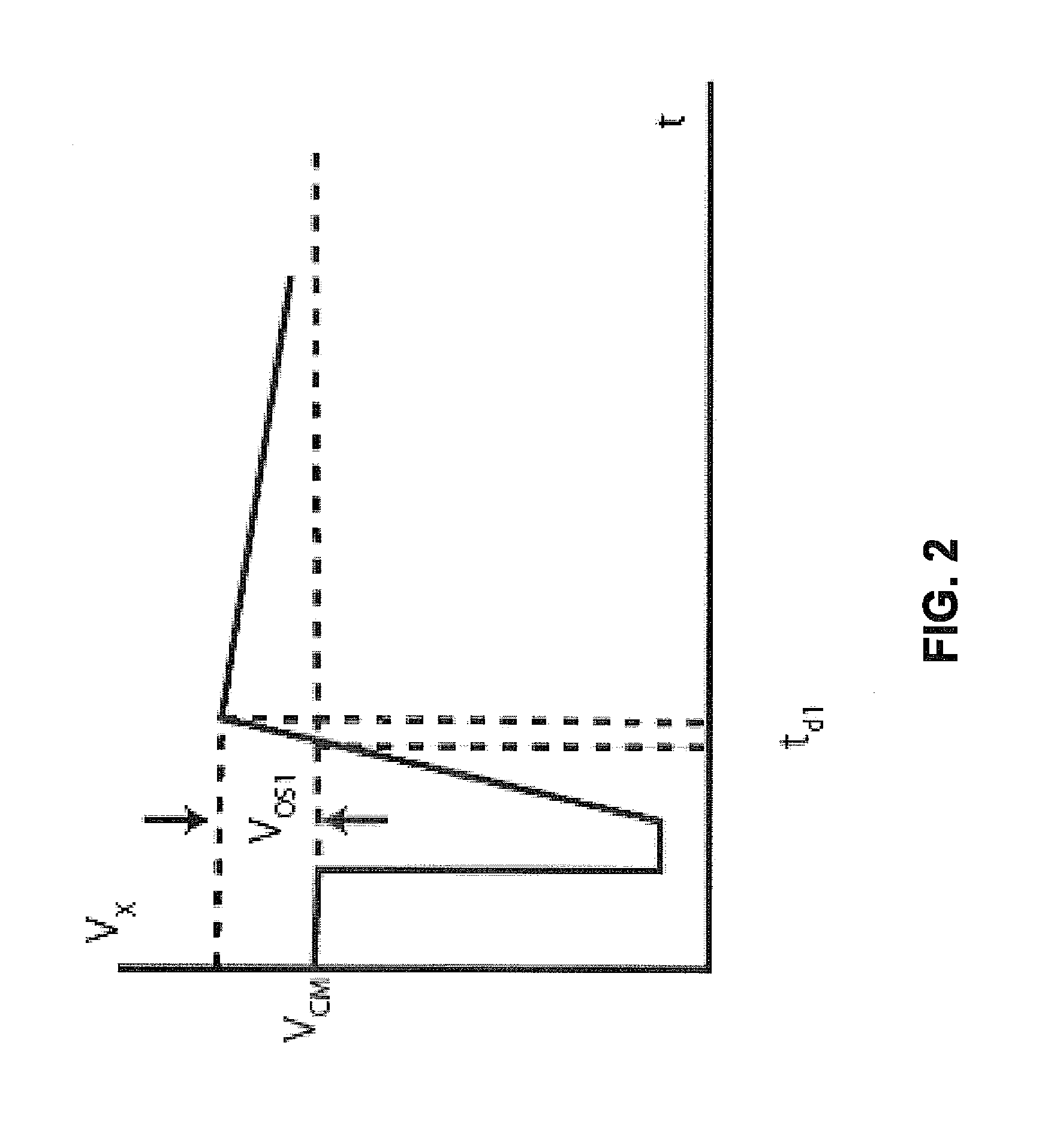
One way to measure the coarse phase overshoot is a direct measurement by monitoring at the input vX of the threshold detector. If the threshold detector had zero delay, the differential input of the zero-crossing detector would be zero at the instant the zero-crossing detector trips. In reality, the finite delay causes the threshold detector to trip past the point where the differential input voltage vX of the threshold detector is zero. Therefore, the differential input voltage vX of the threshold detector at the instant it trips is the measure of the delay and consequential overshoot. This voltage can be directly measured by, for instant, an A / D converter. The A / D converter can measure the voltage vX once every number of samples, thus a slow A / D converter such as a delta-sigma A / D converter can be used. The overshoot can be then compensated in a feedback calibration loop. In the present invention shown in FIG. 10, overshoot compensation capacitors 51, 52, and a digital-to-analog c...
fifth embodiment
the present invention is illustrated in FIG. 15. The offset of the threshold detector 43 is made digitally adjustable. The current sources 41 and 45 are enabled during the coarse phase to produce a coarse ramp and the current sources 42 and 46 are enabled during the fine phase to produce a fine ramp. The coarse phase overshoot is indirectly measured and adjusted such that the threshold detector 43 trips at the optimum time (the solid trace FIG. 11). The offset of the threshold detector is adjusted to achieve the optimum overshoot. An automatic timing-based calibration of the offset is used to achieve optimum overshoot. The calibration is done by monitoring the fine phase threshold crossing instant. The digital controller compares the output of the threshold detector 43 with the desired phase φ. If the threshold crossing occurs later than the desired phase φ, the coarse phase overshoot is too large. In that case, the offset is decremented in the threshold detector 43. This reduces th...
PUM
 Abstract
Description
Claims
Application Information