Circuit and Method for Controlling Light Emitting Device, and Integrated Circuit Therefor

a technology of light emitting devices and circuits, applied in the direction of electric variable regulation, process and machine control, instruments, etc., can solve the problem that devices cannot be integrated into the integrated circui

Inactive Publication Date: 2011-07-14
RICHTEK TECH
View PDF10 Cites 37 Cited by
  • Summary
  • Abstract
  • Description
  • Claims
  • Application Information

AI Technical Summary

Benefits of technology

[0020]In yet another perspective of the present invention, it provides a method for controlling a light emitting device in a light emitting device channel, and the method includes: providing a transistor switch in the light emitting device channel, the transistor switch receiving a control voltage VG; providing a current source circuit in the integrated to control a current through the light emitting device channel, the current source requiring a minimum operation voltage VR for normal operation; causing the control voltage VG to be higher than a reference voltage VH; determining a relationship between a voltage VS at a current outflow end of the transistor switch and the voltage VR; and adjusting a voltage supplied to the light emitting device channel according to the determination result.

Problems solved by technology

However, such devices can not be integrated into the integrated circuit 20, but need to be provided outside of the integrated circuit 20.

Method used


Image

  • Circuit and Method for Controlling Light Emitting Device, and Integrated Circuit Therefor
  • Circuit and Method for Controlling Light Emitting Device, and Integrated Circuit Therefor
  • Circuit and Method for Controlling Light Emitting Device, and Integrated Circuit Therefor

Examples


Embodiment Construction

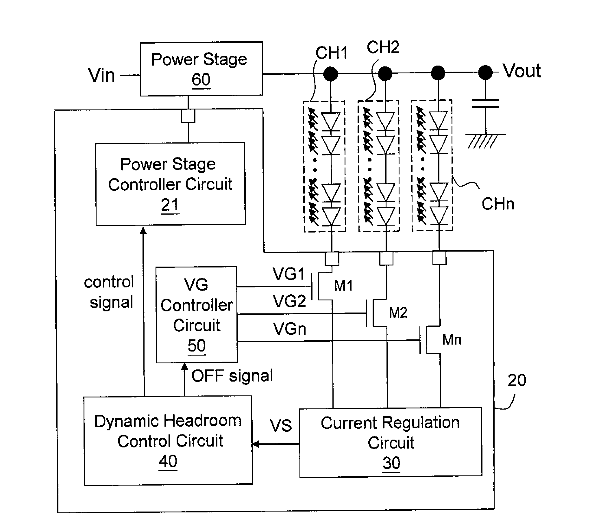
[0041]FIG. 4 shows the first embodiment of the present invention. The present invention integrates current source circuits CS1-CSn into the integrated circuit 20, and provides transistor switches M1-Mn in the LED channel CH1-CHn, respectively, wherein the gates of these transistor switches M1-Mn are controlled by a voltage VG. The voltage VG for example can be a constant voltage or a periodical square-wave signal. When the voltage VG is a square-wave signal, the average current of each LED channel can be adjusted according to the duty ratio of the voltage VG, that is, to adjust the brightness of the LED by the duty ratio of the voltage VG. Because the gate voltage of each transistor switch M1-Mn is VG, the highest voltage at the source of each transistor switch M1-Mn will not be higher than VG. Thus, the transistor switches M1-Mn provide a function to block high voltage, such that the devices forming the current source circuits CS1-CSn can be made of low voltage devices which can be...


PUM


Abstract

The present invention provides a transistor switch on a light emitting device channel, the transistor switch receiving a control voltage VG. A current source circuit controls the current on the light emitting device channel, the current source circuit requiring a minimum voltage VR for normal operation. The present invention further provides a dynamic headroom controller circuit which compares a voltage VS at a current outflow end of the transistor switch with the voltage VR to determine the relationship between the voltage VS and the voltage VR when the control voltage VG is higher than a reference voltage VH, and adjusts the voltage difference between the voltage VS and the voltage VR accordingly.

Description

CROSS-REFERENCE[0001]The present invention is a continuation-in-part application of U.S. Ser. No. 12 / 579,802, filed on Oct. 15, 2009.BACKGROUND OF THE INVENTION[0002]1. Field of Invention[0003]The present invention relates to a circuit and a method for controlling a light emitting device, and particularly to such circuit and method which are capable of reducing the pin number of an integrated circuit and are capable of dynamically adjusting the output voltage to achieve optimal power utilization. The present invention also relates to an integrated circuit for use therein.[0004]2. Description of Related Art[0005]Referring to FIG. 1, conventionally, a light emitting device controller circuit includes an integrated circuit 20, wherein the integrated circuit 20 includes a power stage controller circuit 21 for controlling the operation of a power transistor in a power stage circuit 60 to convert an input voltage Vin to an output voltage Vout for supplying to multiple channels of light em...

Claims


Application Information

Patent Timeline
Patent Type & Authority Applications(United States)
IPC IPC(8): H05B37/02
CPCH05B33/0815Y02B20/347H05B33/0887H05B33/0827H05B45/50H05B45/46Y02B20/30H05B45/3725
Inventor HUANG, TSUNG-WEILIN, SHUI-MUYEUNG, NANG-CHINGLIU, TI-TIYANG, HUAN-CHIEN
Owner RICHTEK TECH
Why Eureka
Try Eureka