

Hair iron
- Summary
- Abstract
- Description
- Claims
- Application Information
AI Technical Summary
Benefits of technology
Problems solved by technology
Method used
Image

Examples
Embodiment Construction
[0027]Reference will now be made in greater detail to a preferred embodiment of the invention, an example of which is illustrated in the accompanying drawings. Wherever possible, the same reference numerals will be used throughout the drawings and the description to refer to the same or like parts.
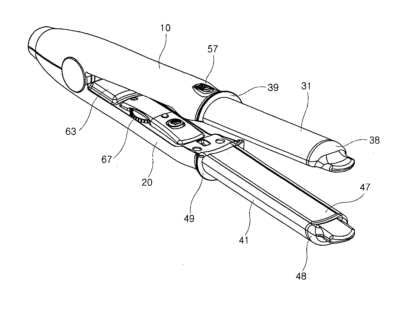
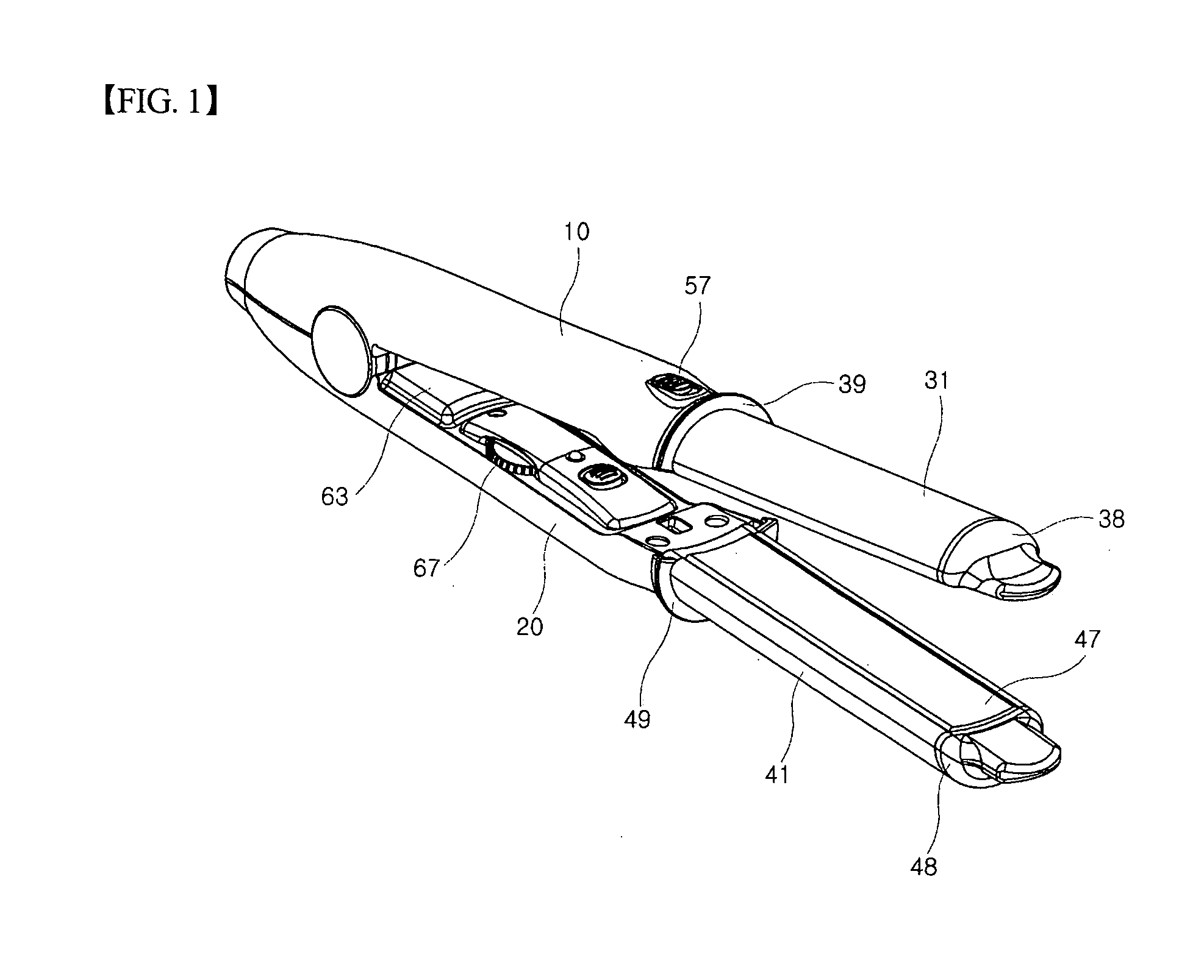
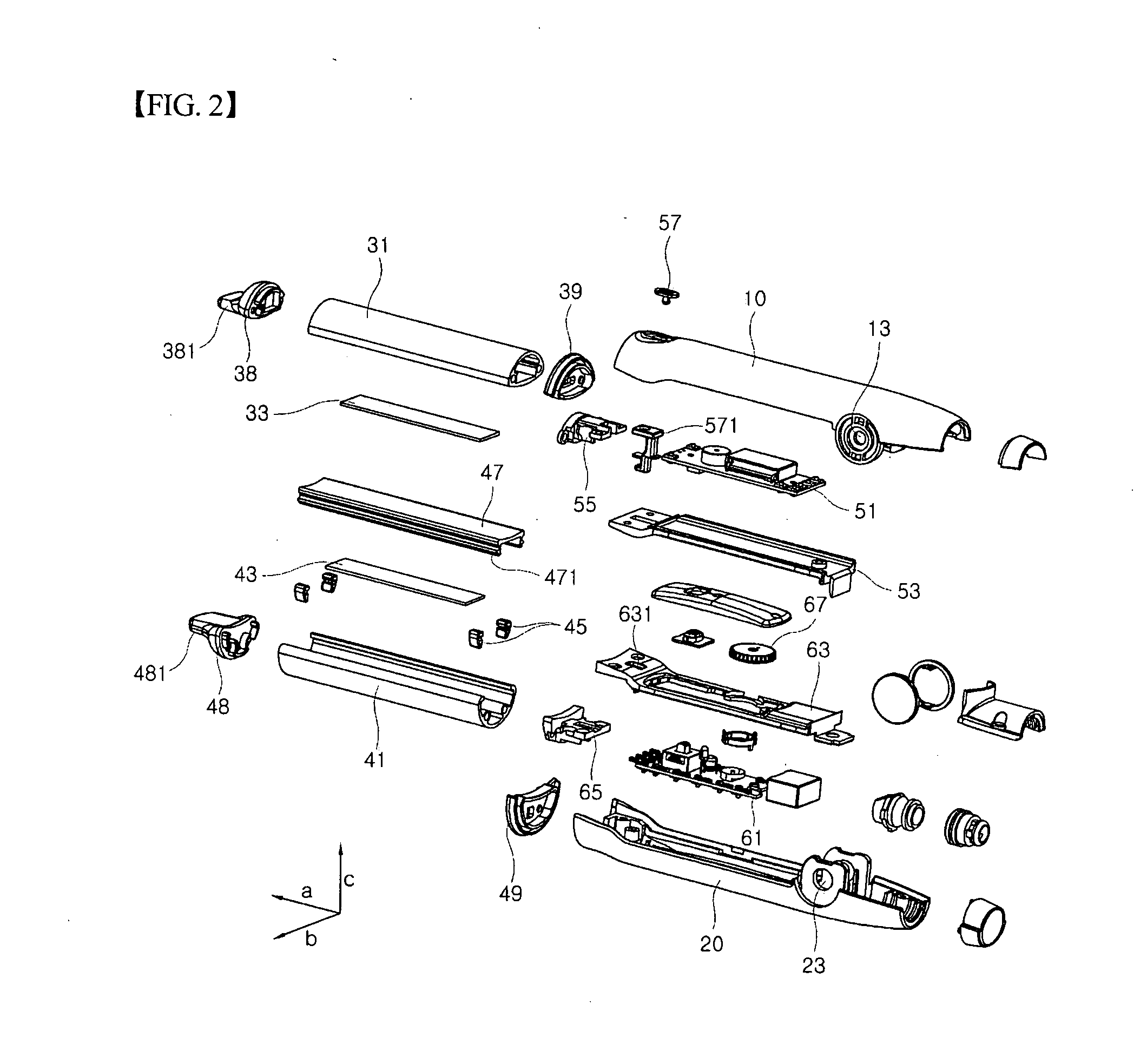
[0028]FIG. 1 is a perspective view illustrating a hair iron according to an embodiment of the present invention, and FIG. 2 is an exploded perspective view illustrating the hair iron according to an embodiment of the present invention.
[0029]A grip portion of the hair iron of the present invention has the shape similar to the conventional plate type hair iron. Upper and lower casings 10 and 20 define the grip portion and are coupled, at a first end in the longitudinal direction ‘a’, with each other, using a hinge and a spring installed around the hinge. Not shown in the drawing is an electric wire which is drawn out from the first end and connected to an external power source.
[0030]The uppe...
PUM
 Abstract
Description
Claims
Application Information