Check patentability & draft patents in minutes with Patsnap Eureka AI!

Twisted nematic (TN) based 3D display system and method

a display system and twisted nematic technology, applied in static indicating devices, instruments, non-linear optics, etc., can solve the problems of affecting image display quality, complex tft tn lcd panels, and high cos

Active Publication Date: 2011-07-21
SUPERD TECH CO LTD
View PDF6 Cites 14 Cited by
  • Summary
  • Abstract
  • Description
  • Claims
  • Application Information

AI Technical Summary

Problems solved by technology

However, TFT TN LCD panels are complex and expensive, and often need to place non-transparent TFT circuit wires and grating wires, etc., on the substrates, which may need to be covered by a black matrix.
However, if removing the black matrix, bright lines may appear along the electrodes, which may also impact image display quality.

Method used


Image

  • Twisted nematic (TN) based 3D display system and method
  • Twisted nematic (TN) based 3D display system and method
  • Twisted nematic (TN) based 3D display system and method

Examples


Embodiment Construction

[0019]Reference will now be made in detail to exemplary embodiments of the invention, which are illustrated in the accompanying drawings. Wherever possible, the same reference numbers will be used throughout the drawings to refer to the same or like parts.

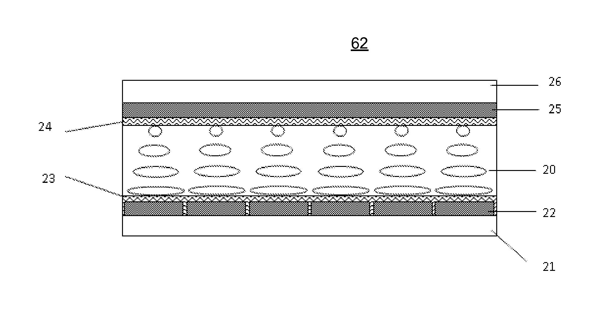
[0020]FIG. 6 shows a structural diagram of an exemplary 3D display system 60. As showed in FIG. 6, 3D display system 60 includes a display device 61, a twisted nematic (TN) liquid crystal panel (TN panel) 62, a first lens array 63, a second lens array 64, and a controller 65. Other components may be added and certain devices may be removed without departing from the principles of the disclosed embodiments. Further, space between various components is shown for illustrative purposes, the disclosed embodiments may or may not have such space.

[0021]3D display system 60 may be used to display three-dimensional (3D) images. Display device 61 may be provided with sets of images to be viewed by a viewer's left eye and right eye separately....


PUM

PropertyMeasurementUnit
threshold voltageaaaaaaaaaa
pulse voltageaaaaaaaaaa
frequencyaaaaaaaaaa

Abstract

A three-dimensional (3D) display apparatus is provided. The 3D display apparatus includes a display device, a twisted nematic (TN) liquid crystal panel, and a lens unit. The display device is configured to output first polarized lights of an image. The TN liquid crystal panel is coupled to the display device and containing a plurality of controllable pixel display areas to receive the polarized lights with a first polarization direction from the display device. Each pixel display area is capable of being in a first state in which the first polarization direction is transformed into a second polarization direction different from the first polarization direction and a second state in which the first polarization direction is maintained. Further, the lens unit is coupled to the TN liquid crystal panel and is configured to guide the polarized lights with the second polarization direction to pass through and to guide polarized lights with the first polarization direction into predetermined transmitting directions for 3D display.

Description

CROSS-REFERENCES TO RELATED APPLICATIONS[0001]This application claims the priority of PCT patent application No. PCT / CN2010 / 070290 filed on Jan. 20, 2010, the entire contents of which are incorporated herein by reference.FIELD OF THE INVENTION[0002]The present invention generally relates to twisted nematic (TN) display technologies and, more particularly, to the methods and systems for three dimensional (3D) display based on TN liquid crystal panels.BACKGROUND[0003]Nowadays, twisted nematic (TN) LC Panel (or TN LC cell) is being widely used in various fields, especially in display technologies. FIG. 1 illustrates a conventional TN LC panel. Glass substrate 11 and glass substrate 12 are arranged in parallel with a predetermined distance therebetween. On the inner surfaces of substrate 11 and substrate 12, transparent electrodes 13 and 14 are provided respectively. Further, on the outer surfaces of the electrodes 13 and 14, alignment layers 15 and 16 are provided respectively, and the...

Claims


Application Information

Patent Timeline
Patent Type & Authority Applications(United States)
IPC IPC(8): G02F1/1335
CPCG02F1/133526G02F1/134309G02F1/1396G09G2300/023G09G3/20G09G3/3622G09G3/003
Inventor GE, ZHANGGUO, FUZHONG
Owner SUPERD TECH CO LTD
Features
  • R&D
  • Intellectual Property
  • Life Sciences
  • Materials
  • Tech Scout
  • Unparalleled Data Quality
  • Higher Quality Content
  • 60% Fewer Hallucinations
Learn More