Method for protecting a pseudo-wire

a pseudo-wire and protection technology, applied in the field of packet-switched networks, can solve the problems of long restoration time, negative impact on service quality, drawback of consuming network resources, etc., and achieve the effect of improving network responsiveness, reducing the quantity of data lost, and improving the restoration tim

Active Publication Date: 2011-07-21
MONARCH NETWORKING SOLUTIONS LLC
View PDF9 Cites 11 Cited by
  • Summary
  • Abstract
  • Description
  • Claims
  • Application Information

AI Technical Summary

Benefits of technology

Installing a datastream switching function in the item of switching equipment improves the restoration time when a failure is detected occurring in the first item of input terminal equipment.
The consequence of this is an improvement in the network responsiveness because the switchover occurs as close as possible to the failure. Thus, the failure of the first item of input terminal equipment is dealt with more rapidly, the information not having to cross the network to the item of output terminal equipment before being handled. Thus, the switchover of the datastream to the third link, established between the item of switching equipment and the second item of input terminal equipment and constituted with the second link of the backup pseudo-wire, occurs more rapidly.
Such a solution reduces the quantity of data lost following the failure of the first item of input terminal equipment.

Problems solved by technology

The result of this is a lengthening of the restoration time in the event of failure of an item of input equipment having a negative impact on the quality of service.
Moreover, such a solution has the drawback of consuming network resources such as, for example, processing resources in the items of equipment (storage memory capacity, computing capacity, etc.), the signaling streams for the purpose of establishing the two pseudo-wires, the bandwidth, notably between the item of switching equipment and the item of output terminal equipment.

Method used


Image

  • Method for protecting a pseudo-wire
  • Method for protecting a pseudo-wire
  • Method for protecting a pseudo-wire

Examples


Embodiment Construction

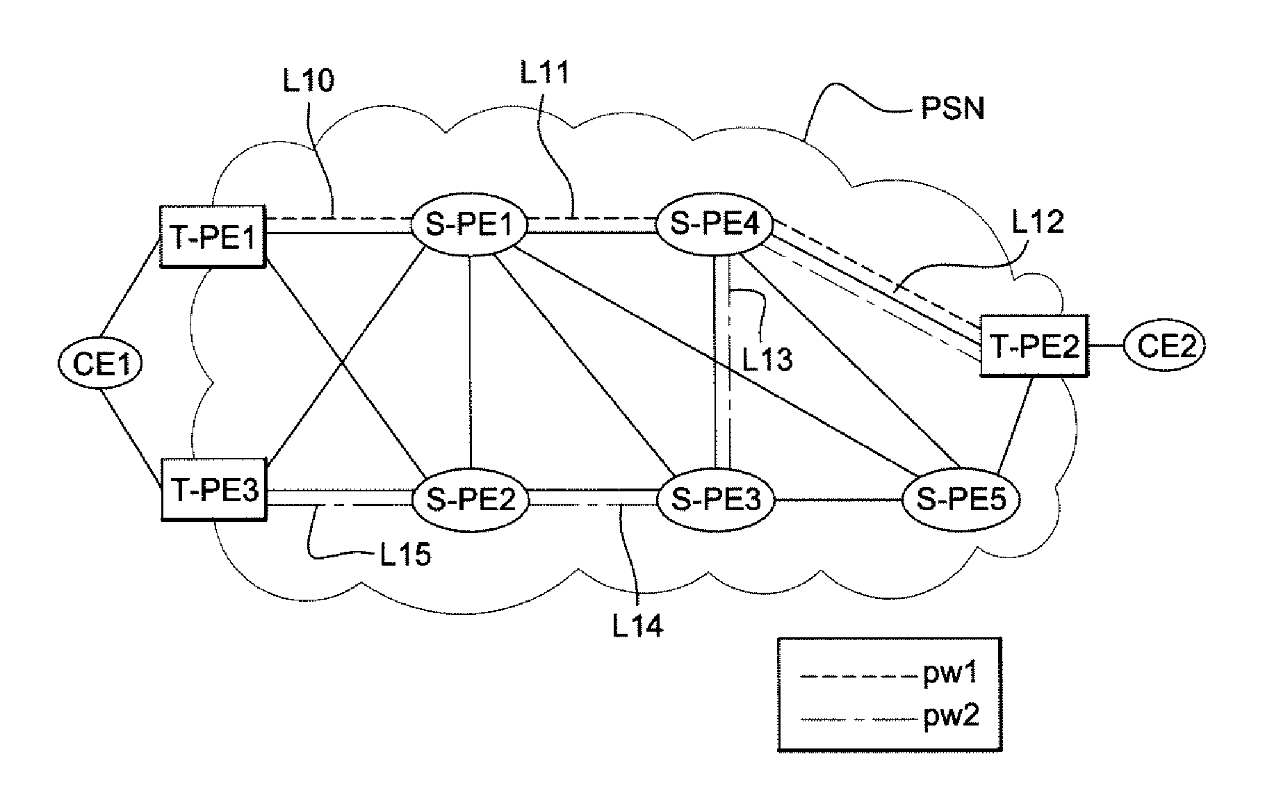
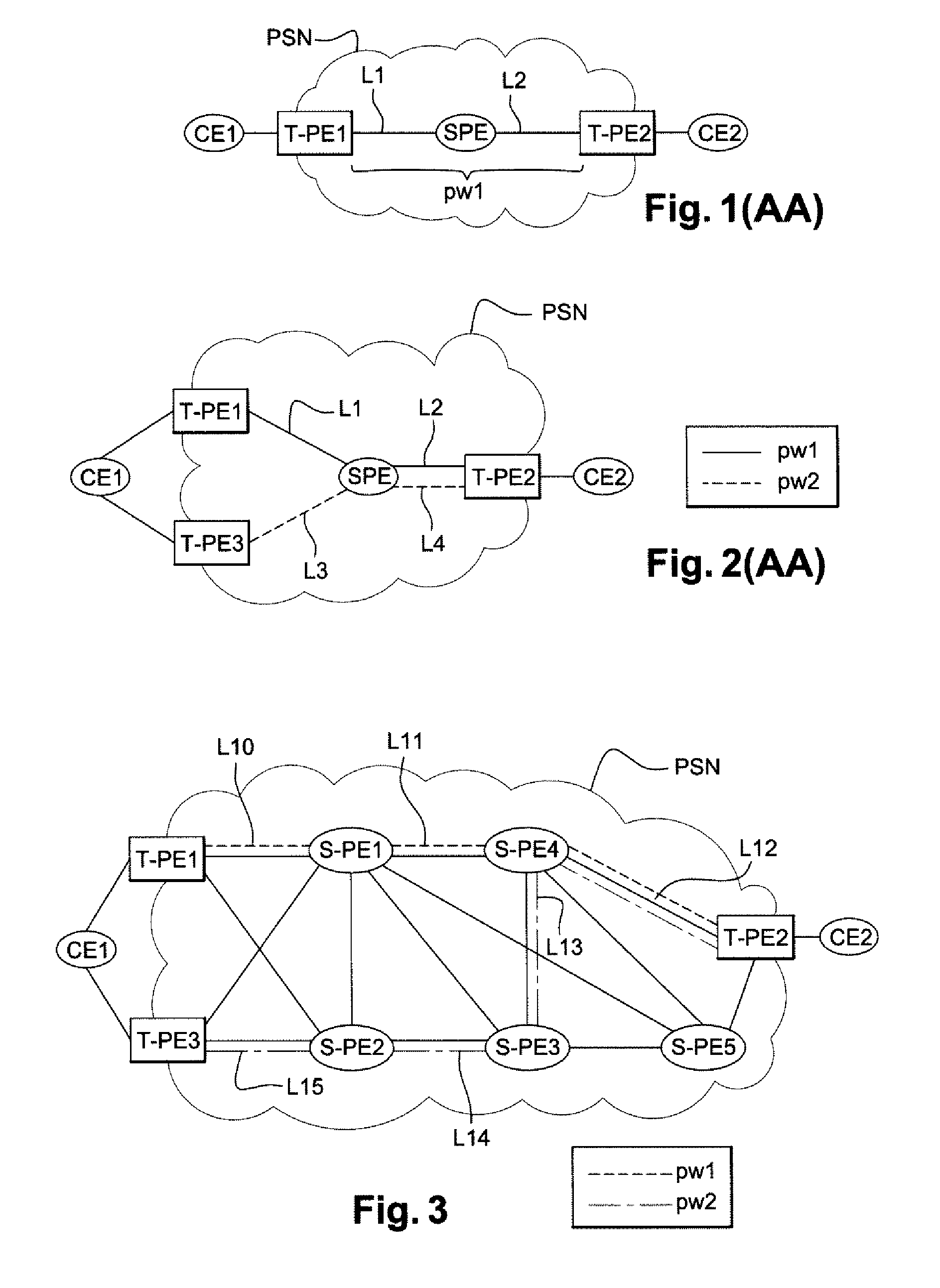
FIG. 3 represents a packet-switched network PSN comprising a plurality of items of terminal equipment T-PE1, T-PE2 and T-PE3 and a plurality of items of switching equipment S-PE1 to S-PE5. In such a network, a link is established between a first item of input terminal equipment T-PE1, an item of output terminal equipment T-PE2 and a second item of input terminal equipment T-PE3, each of these three items of terminal equipment being placed on the edge of the packet-switched network PSN.

With reference to this figure, a first link L10 is established between the first item of input terminal equipment T-PE1 and a first item of switching equipment S-PE1 belonging to the network PSN. A second link L11 is established between the first item of switching equipment S-PE1 and a second item of switching equipment S-PE4. A third link L12 is established between the second item of switching equipment S-PE4 and the item of output terminal equipment T-PE2. The first link L10, the second link L11 and ...


PUM


Abstract

A method and apparatus are provided for establishing a first pseudo-wire between a first item of input terminal equipment and an item of output terminal equipment, used by the first item of input terminal equipment. The method includes a step of transmitting a first message requesting establishment of the first pseudo-wire to an item of switching equipment, the first pseudo-wire to be established consisting of a first link between the first item of input terminal equipment and the item of switching equipment and of a second link between the item of switching equipment and the item of output terminal equipment. In such a method, the first establishment-request message also includes a request to establish at least one backup pseudo-wire consisting of the second link and of a third link to be established between the item of switching equipment and a second item of input terminal equipment.

Description

STATEMENT REGARDING FEDERALLY SPONSORED RESEARCH OR DEVELOPMENTNone.THE NAMES OF PARTIES TO A JOINT RESEARCH AGREEMENTNone.FIELD OF THE DISCLOSUREThe disclosure is situated in the field of telecommunications, and more particularly, but not exclusively, the field of packet-switched networks.BACKGROUND OF THE DISCLOSUREIn a packet-switched network, the data to be transmitted take the form of packets processed by items of network equipment until they reach their destination. All of the packets to be transmitted constitute a datastream.An example of technology used in packet-switched networks to convey data packets is the MPLS (MultiProtocol Label Switching) technology. The MPLS technology proposes adding, in the header of the data packets, one or more labels containing information allowing an item of network equipment to determine the next item of equipment through which a packet is to travel in order to reach its destination. The MPLS technology is described in greater detail in a doc...

Claims


Application Information

Patent Timeline
Patent Type & Authority Applications(United States)
IPC IPC(8): H04L12/26H04L12/56
CPCH04L45/00H04L45/10H04L45/68H04L45/28H04L45/50H04L45/22
Inventor NIGER, PHILIPPEJOUNAY, FREDERIC
Owner MONARCH NETWORKING SOLUTIONS LLC
Why Eureka
Try Eureka