Mechanism for Protecting a Pseudo-Wire

a pseudo-wire and mechanism technology, applied in the field of packet-switched networks, can solve the problems of consuming network resources, consuming network resources, and processing resources in network equipment, so as to improve the responsiveness of the network, improve the restore time on detection, and reduce the quantity of data lost

Active Publication Date: 2010-04-22
MONARCH NETWORKING SOLUTIONS LLC
View PDF3 Cites 36 Cited by
  • Summary
  • Abstract
  • Description
  • Claims
  • Application Information

AI Technical Summary

Benefits of technology

[0033]Providing in the intermediate router a function for detecting a fault affecting the first output router and a function for switching the data stream improves the restore time on detection of a fault affecting the first output router.
[0034]This improves the responsiveness of the network because detection occurs as close as possible to the fault. Accordingly, a fault affecting the first output router is detected more quickly, as the information does not have to cross the network as far as the input router before being processed. The function for switching the data stream also being a function of the intermediate router, switching the data stream to the third link, set up between the intermediate router and the second output router and with the first link constituting the back-up pseudo-wire, occurs faster because it is triggered on detection of the fault by the intermediate router.
[0035]This kind of solution reduces the quantity of data lost following a fault affecting the first output router.

Problems solved by technology

However, the MPLS protocol can process only packets conforming to the Internet Protocol (IP).
However, this kind of solution has the drawback of consuming network resources, for example processing resources in the network equipments (storage capacity, computation capacity, etc.), signaling streams for setting-up two pseudo-wires, and bandwidth, especially between the input router and the intermediate router.
This increases the restore time in the event of a fault affecting an output router, with a negative impact on quality of service.

Method used


Image

  • Mechanism for Protecting a Pseudo-Wire
  • Mechanism for Protecting a Pseudo-Wire
  • Mechanism for Protecting a Pseudo-Wire

Examples


first embodiment

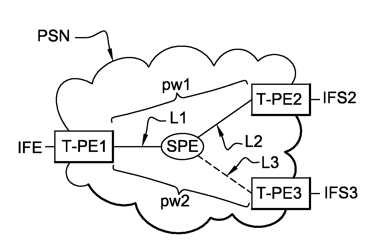
[0072]FIG. 7 represents a timing diagram of the exchange of messages between the input router T-PE1, the intermediate router S-PE, the first output router T-PE2, and the second output router T-PE3 when broadcasting data streams in the invention.

[0073]A data stream D1 is sent by the input router T-PE1 to the first output router T-PE2. This first data stream is broadcast over the network PSN by means of the first pseudo-wire pw1.

[0074]To ensure continuity of service, the input router T-PE1 includes a function for detecting a fault affecting the first output router T-PE2. In order to detect this kind of fault, the input router T-PE1 regularly exchanges “echo” messages with the first output router T-PE2 and with the intermediate router S-PE.

[0075]If the input router does not receive a response to an “echo” message, it deduces that the first output router T-PE2 or the intermediate router S-PE is faulty.

[0076]If the faulty router is the first output router T-PE1, it then sends the interme...

second embodiment

[0078]FIG. 8 is a timing diagram of the exchange of messages between the input router T-PE1, the intermediate router S-PE, the first output router T-PE2, and the second output router T-PE3 when broadcasting data streams in the invention.

[0079]A data stream D1′ is sent by the input router T-PE1 to the first output router T-PE2. This data stream is broadcast over the network PSN by the first pseudo-wire pw1.

[0080]To ensure continuity of service, the intermediate router S-PE includes a function for detecting a fault affecting the first output router T-PE2. In order to detect such a fault, the intermediate router S-PE regularly exchanges “echo” messages with the first output router T-PE2.

[0081]If the intermediate router does not receive a response to its “echo” message, it deduces that the first output router T-PE2 is faulty. It then switches the data streams coming from the input router T-PE1 to the link L3 and advises the input router T-PE1 of this.

[0082]Thus a data stream D2′ sent by...


PUM


Abstract

A method is provided for setting up at least two pseudo-wires able to broadcast a stream of data, wherein a first pseudo-wire is set up between an input router of a packet-switched network and first output router of the packet-switched network, and a second pseudo-wire is set up between the input router and a second output router of the packet-switched network. A first link of the first pseudo-wire is set up between the first output router and an intermediate router of the packet-switched network. A second link of the second pseudo-wire is set up between the second output router and the intermediate router. A third link of both pseudo-wires is set up between the intermediate router and the input router.

Description

CROSS-REFERENCE TO RELATED APPLICATIONS[0001]This Application is a Section 371 National Stage Application of International Application No. PCT / FR2008 / 050324, filed Feb. 26, 2008 and published as WO 2008 / 110735 on Sep. 18, 2009, not in English.STATEMENT REGARDING FEDERALLY SPONSORED RESEARCH OR DEVELOPMENT[0002]None.THE NAMES OF PARTIES TO A JOINT RESEARCH AGREEMENT[0003]None.FIELD OF THE DISCLOSURE[0004]The field of the disclosure is telecommunications, and more particularly packet-switched networks.BACKGROUND OF THE DISCLOSURE[0005]In a packet-switched network, data is transmitted in the form of packets processed by routers of the network until they reach their destination. Together the packets for transmission constitute a data stream.[0006]One example of a technology used for routing data packets in packet-switched networks is the multi-protocol label switching (MPLS) technology. The MPLS technology adds one or more labels to the data packet headers, said labels containing inform...

Claims


Application Information

Patent Timeline
Patent Type & Authority Applications(United States)
IPC IPC(8): H04L12/56
CPCH04L45/22H04L45/10
Inventor JOUNAY, FREDERICNIGER, PHILIPPECAUVIN, ARNAUD
Owner MONARCH NETWORKING SOLUTIONS LLC
Why Eureka
Try Eureka